Table of Contents |
Ethernet is a Layer 2 (Data Link) protocol that enables us to build local area networks (LANs). It is important to understand Ethernet cabling, which resides at Layer 1 (Physical), because it is the physical infrastructure of most LANs. There are different types of wiring standards available:
If you look inside a UTP or STP network cable, you will find four pairs of wires twisted together to prevent crosstalk; they are also twisted like this to help prevent EMI and electronic eavesdropping. The same pins have to be used on the same colors throughout a network to receive and transmit.
TIA/EIAT568A and TIA/EIAT568B are two wiring standards created by the Telecommunications Industry Associate (TIA) and the Electronics Industry Association (EIA) to specify which wire colors go in which positions in the connectors. Over the years, some network jacks have been pinned with the T568A standard and some have used the T568B standard, which can cause a bit of confusion if you do not know what you are looking at in your network. Generally, the T568B standard is deployed in a typical commercial building cabling installation, while the T568A standard is found almost exclusively in the buildings of US Federal government agencies. In fact, the T568A standard is required for all network cabling projects done under federal contract.
T568A was to be backward compatible with older telephone wires; T568B was designed for better signal isolation and noise protection for more modern networking systems and products.
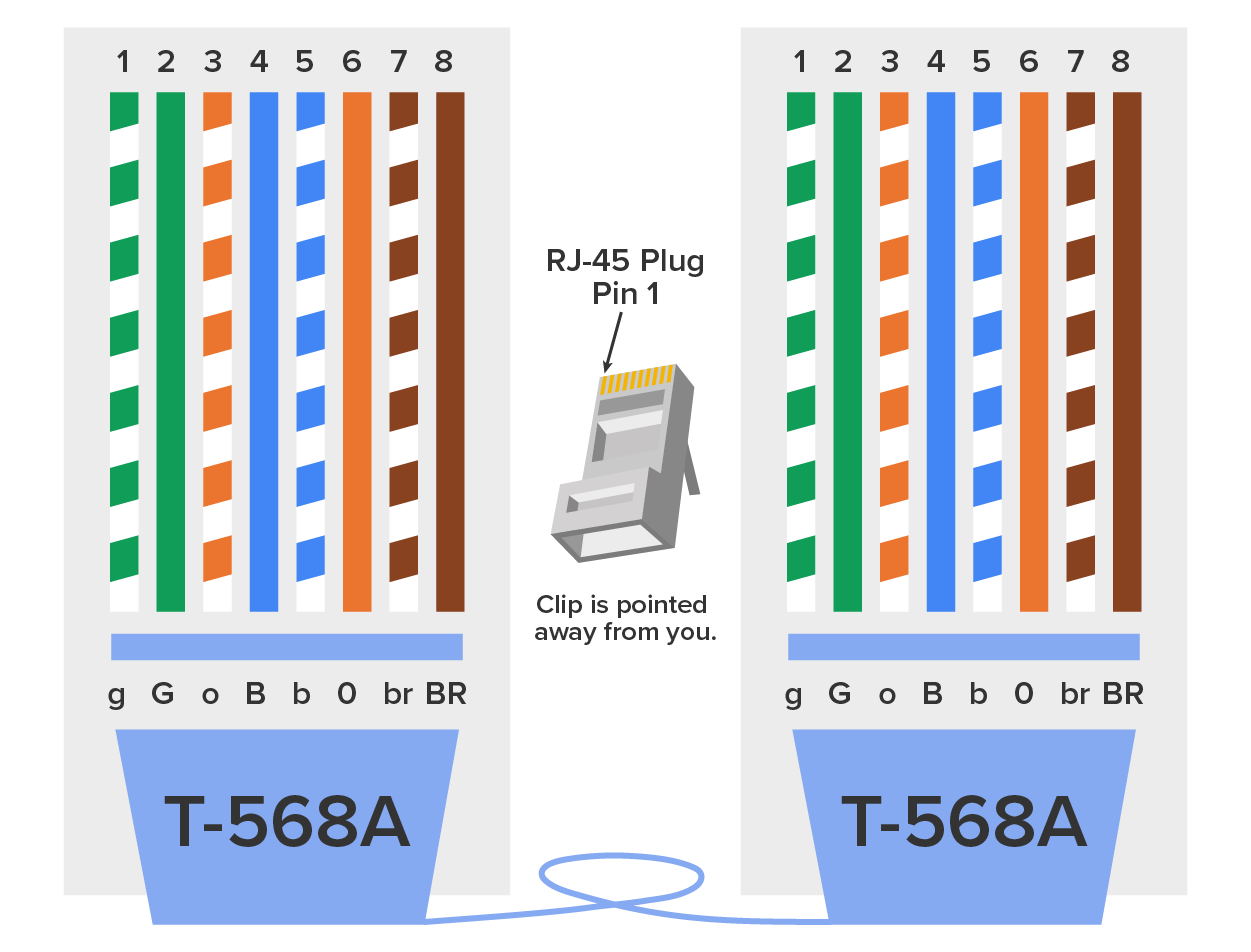
By looking at the diagram of the T568A pinout below, you can see that the green pair is used for pins 1 and 2 but the orange pair is split to pins 3 and 6, separated by the blue pair.
Now take a look at the T568B diagram below. The orange pair is pins 1 and 2 and the green pair is pins 3 and 6, again separated by the blue pair.
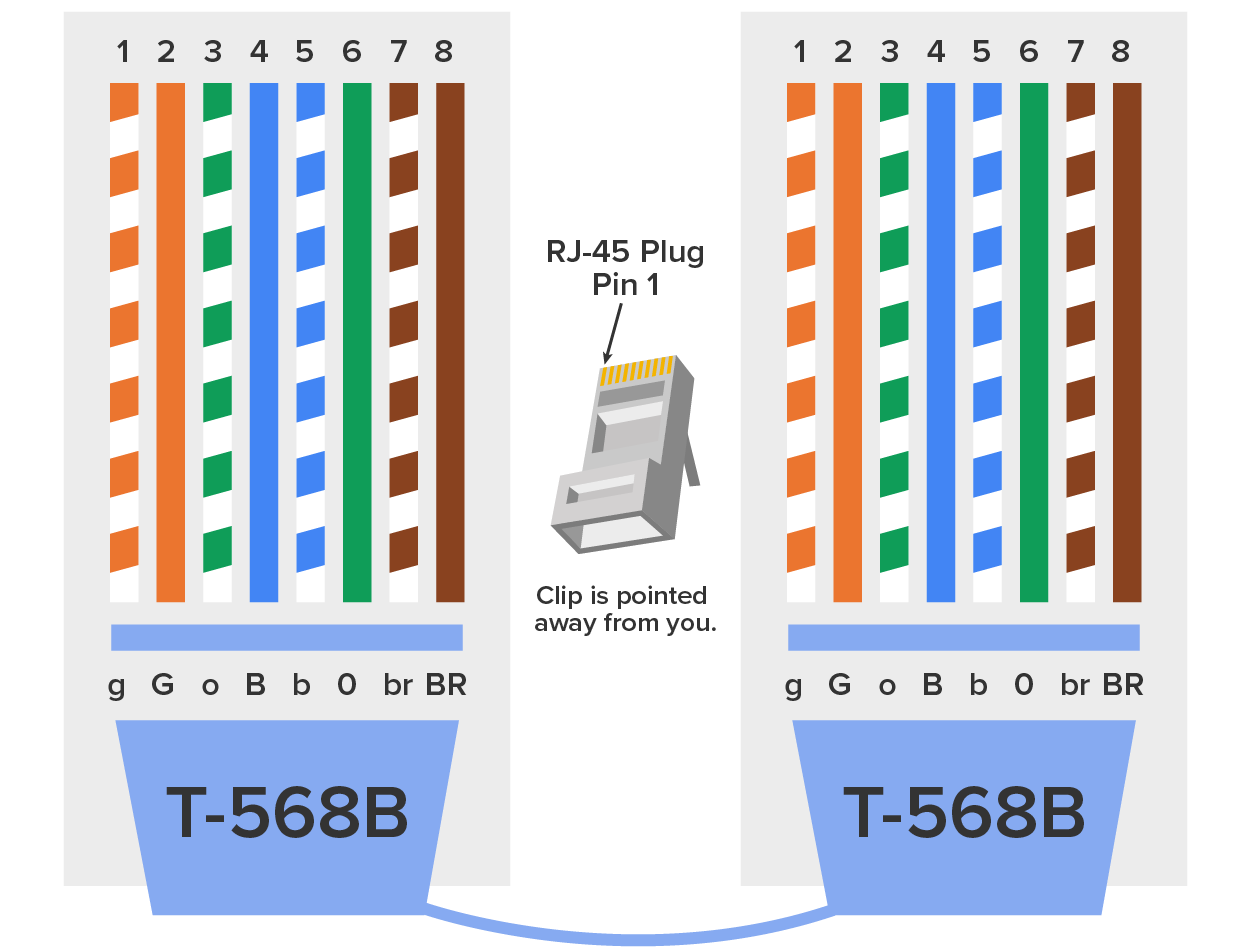
Note that the only difference between T568A and T568B is that the orange and green pairs are swapped on pins 1 and 2, and on pins 3 and 6.
If you are installing new cabling to typical cubicle or office workspaces, you need to use Cat 5e or Cat 6. Voice-over IP (VoIP) uses all eight pins, and it is really common to have voice and data on the same wire at the same time in modern networks, so it is best practice to connect all eight pins. Pins 4, 5, 7, and 8 are used in both standards.
This only leaves the wire pairs to connect to pins 1, 2, 3, and 6 for data. Remember, if we connect the orange-white, orange, green-white, and green wires to pins 1, 2, 3, and 6, respectively, on both sides of the cable, we are using the T568B standard and creating a straight-through cable that is commonly implemented as a patch cable. On the other hand, if we switch from pin 1 to pin 3 and from pin 2 to pin 6 on one side only, we have created a 'crossover cable. Let us take a look.
A straight-through cable is used to connect a host to a switch or hub or a router to a switch or hub. Four out of the eight wires are used in straight-through cable to connect 10 or 100 Mbps Ethernet devices. It is really pretty simple to do this; the graphic below depicts the four wires used in a straight-through Ethernet cable.

Notice that only pins 1, 2, 3, and 6 are used. Connect 1 to 1, 2 to 2, 3 to 3, and 6 to 6 and you will be up and networking in no time. Just remember that this would be a 10Mpbs or 100Mbps Ethernet-only cable. This configuration t would not work with 1000 Mbps Ethernet, voice, ISDN, and so on.
The same four wires are used in this cable, and just as with the straight-through cable, you simply connect the different pins together. Crossover cables can be used to connect these devices:

Notice that instead of connecting 1 to 1, 2 to 2, and so on, we connected pins 1 to 3 and 2 to 6 on each side of the cable. A crossover cable is typically used to connect two switches together, but it can also be used to test communications between two workstations directly, bypassing the switch. A crossover cable is used only in Ethernet UTP installations. You can connect two workstation NICs or a workstation and a server NIC directly with it. If you are trying to match the straight-through and crossover cables with the T568A and T568B standard, here is how it would look:
            T568A+T568A = straight-through
            T568B+T568B = straight-through
            T568A+T568B = crossover
It is best practice to label a crossover cable as such so that no one tries to use it to connect a workstation to the network. If they do that, the workstation will not be able to communicate with the switch and the rest of the network because the transmit and receive pins are crossed. It is also a best practice to carry a crossover cable with you in your tool bag along with your laptop so you are prepared to use it to test is a server’s network interface card (NIC) is functioning correctly, you can just connect your laptop directly to the server’s NIC using your handy crossover cable. You should be able to log in to the server if both NICs are configured correctly.
Use a cable tester to make sure that what you are dealing with is in fact a crossover cable. The tester can also tell you if there is a problem with the cable. The image below hows an inexpensive cable tester for UTP.
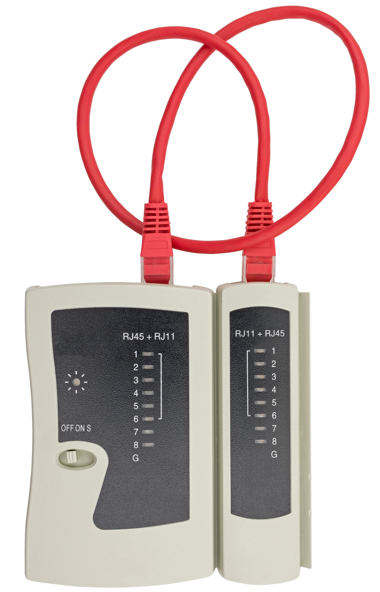
This cost-effective little tool will tell you if you have a straight-through or crossover cable, or even if there is a functional problem with the cable.
Today, many modern networking devices like switches are capable of detecting the cable type that is plugged into a port and change the ports configuration to accommodate the cable. In other words, you can often use a straight-through cable in places that used to require a crossover cable, and the device will autocorrect for it by doing the crossover internally. That said, it remains important to know the traditional uses of crossover and straight-through cables given the large installed base of legacy hardware in some enterprise environments.
In the previous examples of 10BaseT and 100BaseT UTP wiring, only two wire pairs were used, but that’s just not good enough for Gigabit UTP transmission. 1000BaseT UTP wiring (see graphic below) requires four wire pairs and uses more advanced electronics so that each and every pair in the cable can transmit simultaneously. Even so, gigabit wiring is almost identical to my earlier 10/100 Mbps example, except that we will use the other two pairs in the cable.

For a straight-through cable it’s still 1 to 1, 2 to 2, and so on up to pin 8.
Although rolled cable is not used to connect any Ethernet connections together, you can use a rolled Ethernet cable to connect a host EIA-TIA 232 interface to a router console serial communication (COM) port. If you have a Cisco router or switch, you will use this cable to connect your PC, Mac, or a device like an iPad to the Cisco hardware. Eight wires are used in this cable to connect serial devices, although not all eight are used to send information, just as in Ethernet networking. The diagram below shows the eight wires used in a rolled cable.

These are probably the easiest cables to make because you just cut the end off on one side of a straight-through cable, turn it over, and put it back on—with a new connector, of course!
Later in the course, you will be introduced to a device called the CSU/DSU. This device may be your connection to the internet for the enterprise. The type of cable you use to connect to this device from your router depends on the interface types that are available on the router.
The router may connect with several types of serial cables if a T1 connection, which is a WAN connection leased from a telecommunications service provider, is not built into it. If a T1 connection is built into the router, you will use an Ethernet cable. The illustration shows a T1 crossover cable connected to an RJ-45 connector.
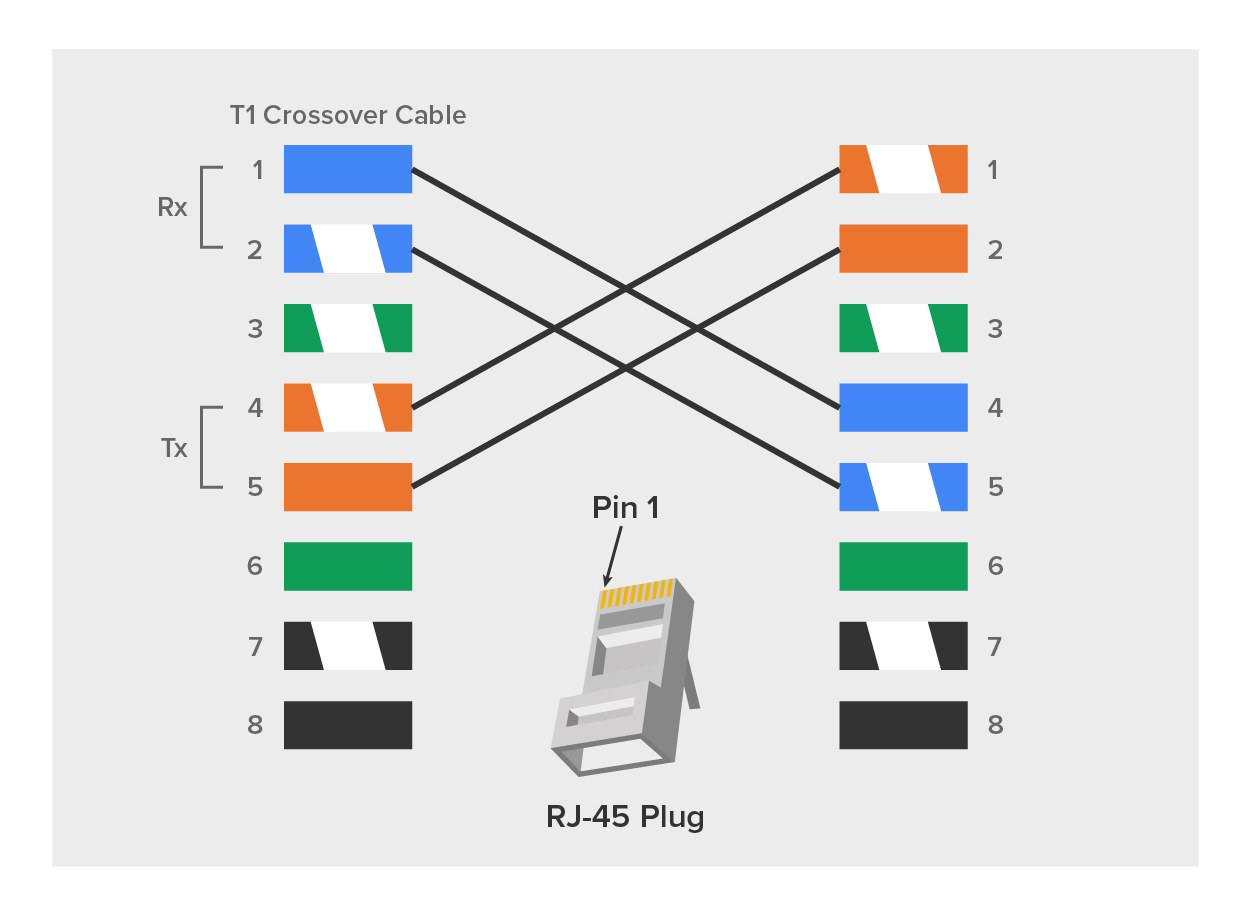
In rare instances, you may need to run a cable between two CSU/DSUs. In that case, you would need a T1 crossover cable. A T1 cable uses pairs 1 and 2, so to connect two T1 CSU/DSU devices back-to-back requires a crossover cable that swaps these pairs. Specifically, pins 1, 2, 4, and 5 are connected to 4, 5, 1, and 2, respectively.
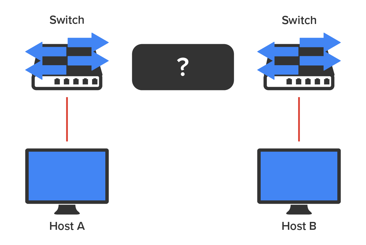
For host A to ping host B, you need a crossover cable to connect the two switches together. But what types of cables are used in the network shown in the following image?
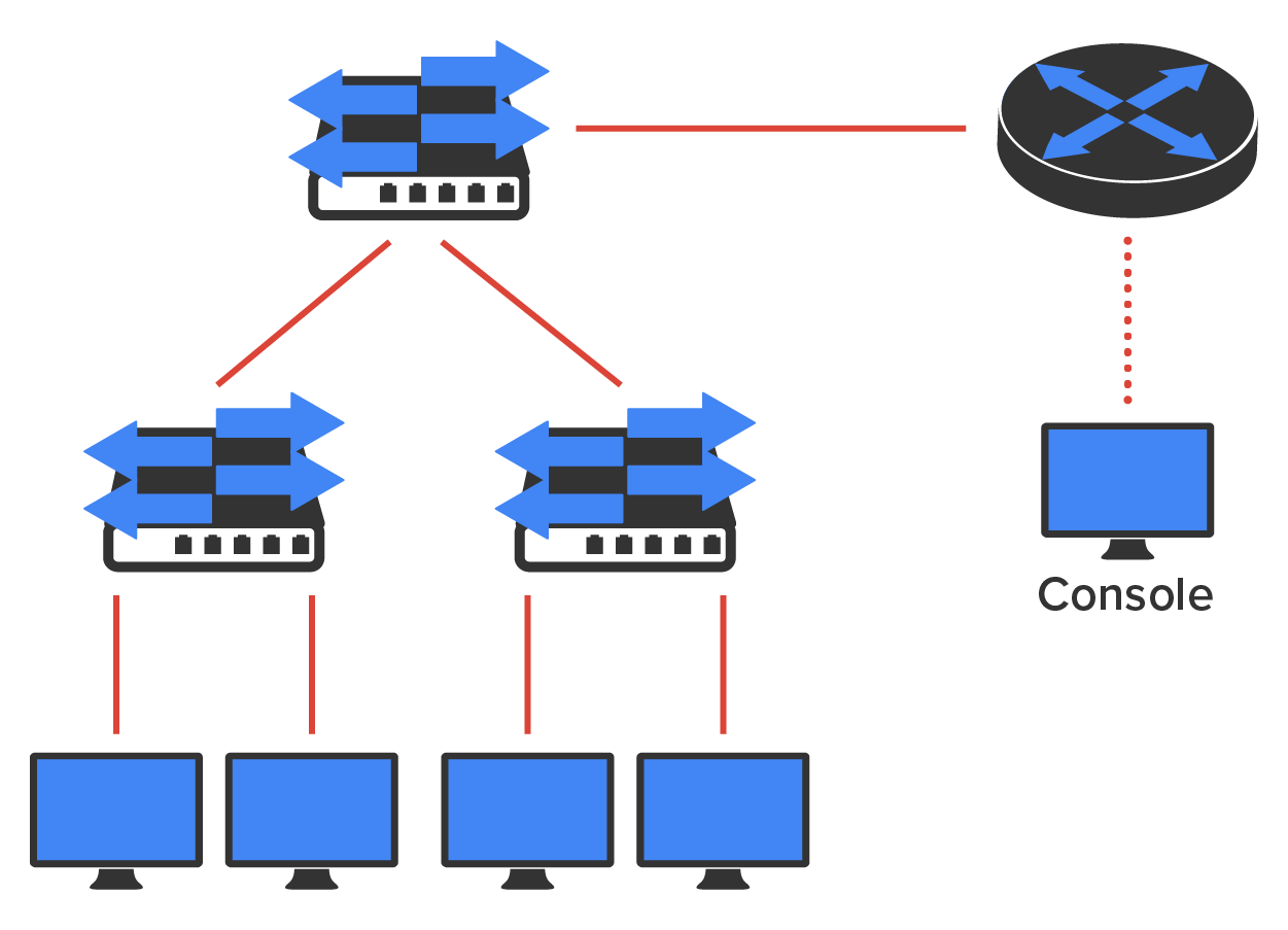
In the diagram above, there are a variety of cables in use. For the connection between the switches, we would clearly use a crossover cable like the one you saw in the earlier example. The trouble is, here we have a console connection that uses a rolled cable. Plus, the connection from the router to the switch is a straight-through cable, which is also what is running between the hosts to the switches.
There are a lot more components that may be in the typical computer network than meets the eye. So, let us go over each of these components and the process of verifying their proper installation.
The main distribution frame (MDF) is a wiring point that is generally used as a reference point for telephone lines entering a building. It is also considered the WAN termination point. It is installed in the building as part of the prewiring, and the internal lines are connected to it. After that, all that is left is to connect the external lines from a telecommunications provider to the other side to complete the circuit. Often, another wireframe called an intermediate distribution frame (IDF) is located in an equipment or telecommunications room. It is connected to the MDF and is used to provide greater flexibility for the distribution of all the communications lines to the building. It is typically a sturdy metal rack designed to hold the bulk of cables coming from all over the building! The MDF is located in the “entrance facility” of telecommunications lines, which is typically in an organization’s data center.
A 25-pair cable consists of 25 individual pairs of wires all inside one common insulating jacket. It is not generally used for data cabling, just for telephone cabling, and especially for backbone and cross-connect cables because it reduces the cable clutter significantly. This type of cable is often referred to as a feeder cable because it supplies signal to many connected pairs.
A 66 block is used for old analog telephone connections. This uses the 25-pair cable we just mentioned and is a standard termination block containing 50 rows, which created an industry standard for easy termination of voice cabling.
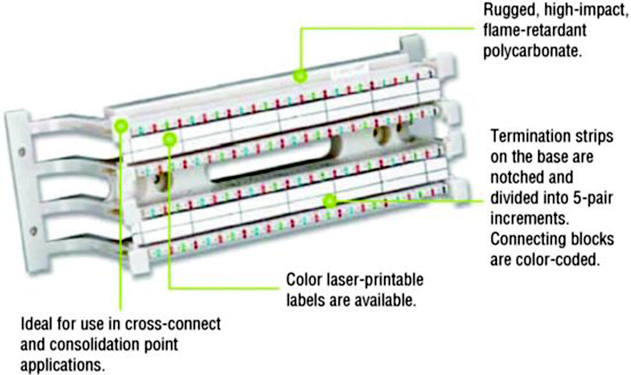
A newer type of wiring distribution point called a 110 block has replaced most telephone wire installations and is also used for computer networking. On one side, wires are connected using a punch down tool; the other side has RJ-11 (for phone) or RJ-45 (for network) connections. You will find 110 blocks in sizes from 25 to more than 500 wire pairs, and some are capable of carrying 1 Gbps connections when used with Category 6 cables. Using Cat 6 with the 110 block may be difficult because of the size of the Cat 6 wiring. The illustration below shows a 110 block and describes each section used in the 110 block.
The demarc (short for demarcation) is the last point of responsibility for the service provider. It is often at the MDF in your building connection, especially if your building is large, but it is usually just an RJ-45 jack that your channel service unit/data service unit (CSU/DSU) connects from your router to wide area network (WAN) connections. We will discuss CSU/DSUs thoroughly later.
When troubleshooting, network admins often test for connectivity on both sides of the demarc to determine if the problem is internal or external. The length of copper or fiber that begins after the demarc but still does not reach all the way up to your office is referred to as a demarc extension.
A smart jack, also called a network interface device (NID) or network interface unit (NIU), is owned by the PSTN and is a special network interface that is often used between the service provider’s network and the internal network. You cannot physically test to an actual demarc because it’s just an RJ-45 jack, but the service provider may install an NID that has power and can be looped for testing purposes. The smart-jack device may also provide for code and protocol conversion, making the signal from the service provider usable by the devices on the internal network like the CSU/DSU.
Source: This content and supplemental material has been adapted from CompTIA Network+ Study Guide: Exam N10-007, 4th Edition. Source Lammle: CompTIA Network+ Study Guide: Exam N10-007, 4th Edition - Instructor Companion Site (wiley.com)