Table of Contents |
A virtual local area network (VLAN) is a logical grouping of network users and resources connected to administratively defined ports on a switch. When you create VLANs, you gain the ability to create smaller broadcast domains within a Layer 2 switched internetwork by assigning the various ports on the switch to different subnetworks. A VLAN is treated like its own subnet or broadcast domain, meaning that frames broadcasted onto the network are only switched between the ports logically grouped within the same VLAN.
The diagram below shows how Layer 2 switched networks are typically designed as flat networks. A flat network is a network with all hosts residing in a single broadcast domain. With this configuration, every broadcast packet transmitted is seen by every device on the network regardless of whether the device needs to receive that data.
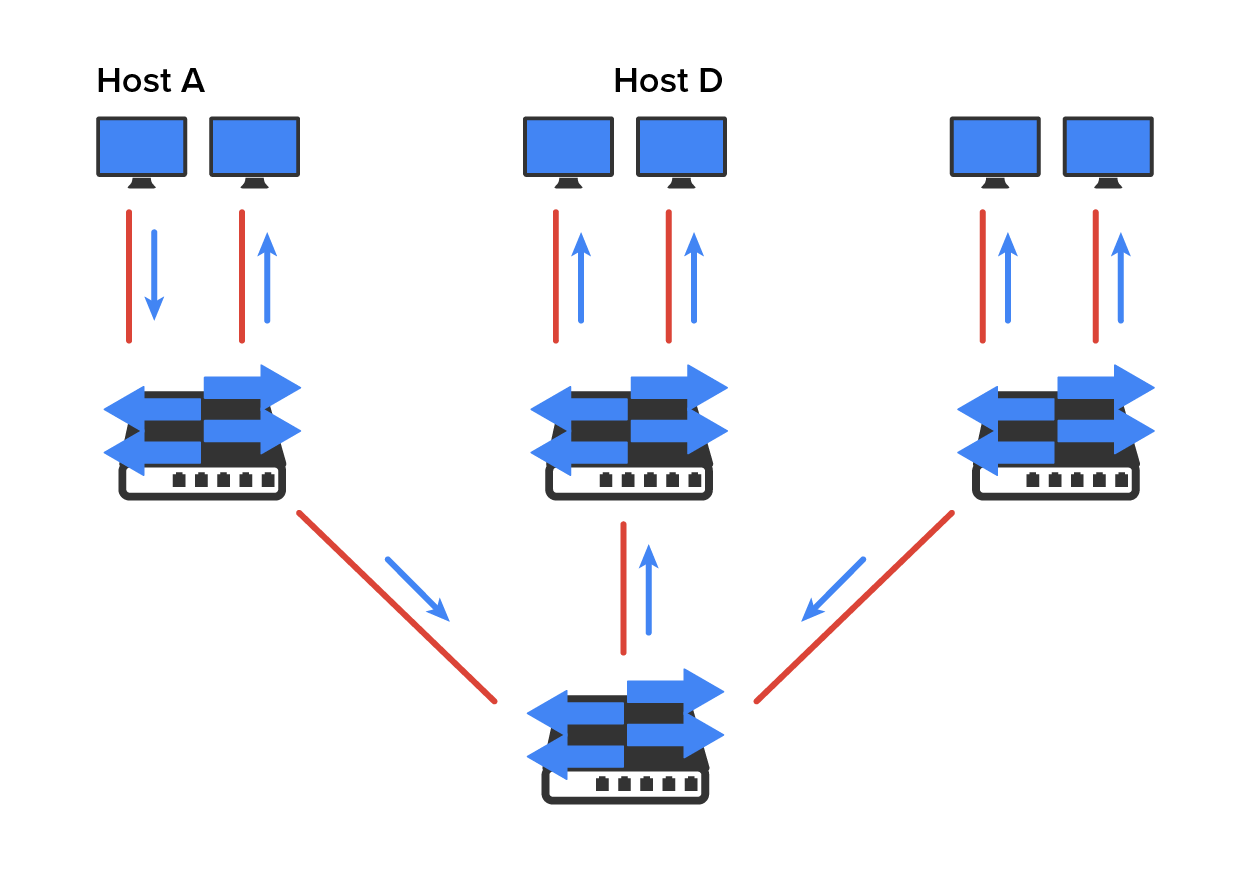
By default, routers allow broadcasts to occur only within the originating network, whereas switches forward broadcasts to all segments. Flat networks are titled such because they have single broadcast domains, not because the actual design is physically flat. In the diagram above, you can see Host A sending out a broadcast and all ports on all switches forwarding it except each port that receives it.
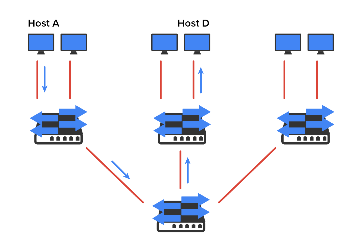
The diagram below pictures a switched network and shows Host A sending a frame with Host D as its destination. What is important here is that the frame is forwarded only out of the port where Host D is located. This is a huge improvement over the old hub networks.
To understand how a VLAN looks to a switch, it is helpful to begin by first looking at a traditional network. The diagram below shows how a network used to be created using hubs to connect physical LANs to a router.
Here, you can see that each network is attached with a hub port to the router (each segment also has its own logical network number, even though this is not obvious looking at the figure). Each host attached to a particular physical network has to match that network’s logical network number in order to be able to communicate on the internetwork. Notice that each department has its own LAN, so if we needed to add new users to, let us say, Sales, we would just plug them into the Sales LAN and they would automatically be part of the Sales collision and broadcast domain. This design actually did work well for many years.
IN CONTEXT
However, there was one major flaw: What happens if the hub for Sales is full and we need to add another user to the Sales LAN? Or what do we do if there is no more physical space for a new employee where the Sales team is located? Let’s imagine that there just happens to be plenty of room over in the Finance section of the building. That new Sales team member will just have to sit on the same side of the building as the Finance people, and we will just plug that user into the hub for Finance.
Doing this obviously makes the new user part of the Finance LAN, which is very bad for many reasons. First and foremost, we now have a major security issue. Because the new Sales employee is a member of the Finance broadcast domain, the new employee can see all the same servers and access all network services that the Finance folks can. Second, for this user to access the Sales network’s services that they need to get their job done, they would have to go through the router to log in to the Sales server, which is not efficient.
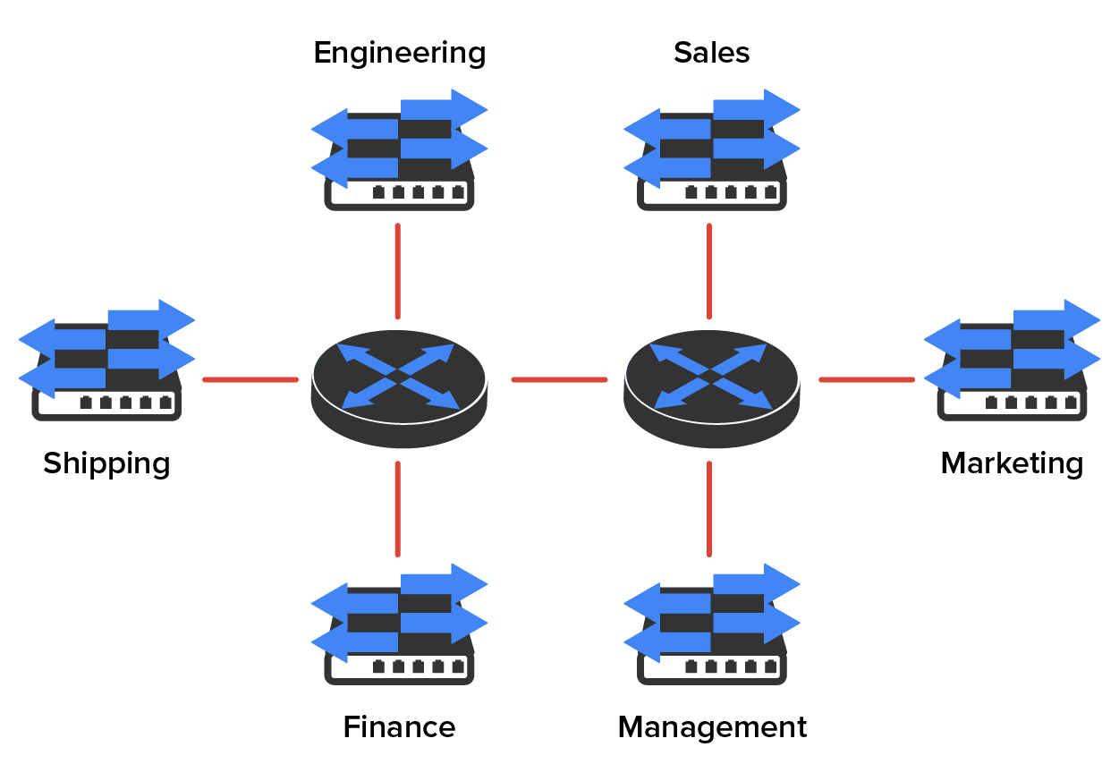
Now, let us look at what a switch accomplishes for us. The diagram demonstrates how switches remove the physical boundary to solve our problem. It also shows how six VLANs (numbered 2 through 7) are used to create a broadcast domain for each department. Each switch port is then administratively assigned a VLAN membership, depending on the host and which broadcast domain it is placed in.
So, now, if we needed to add another user to the Sales VLAN (VLAN 7), we could just assign the port to VLAN 7 regardless of where the new Sales team member is physically located. This illustrates one of the primary advantages to designing your network with VLANs over the old, collapsed backbone design. Now, cleanly and simply, each host that needs to be in the Sales VLAN is merely assigned to VLAN 7.
Now, because each VLAN is considered a broadcast domain, it has got to also have its own subnet number. And if you are also using IPv6, then each VLAN must also be assigned its own IPv6 network number. To avoid getting confused, just keep thinking of VLANs as separate subnets or networks.
When looking at the diagram above, you can see that there are seven VLANs, or broadcast domains, counting VLAN 1 (not shown in the figure). The hosts within each VLAN can communicate with each other but not with anything in a different VLAN because the hosts in any given VLAN act as if they’re actually in a collapsed backbone.
Most of the time, VLANs are created by a system administrator who proceeds to assign switch ports to each one. VLANs of this type are known as static VLANs. If you do not mind doing a little more work when you begin this process, add all the host devices’ hardware MAC addresses into a database so your switches can be configured to assign VLANs dynamically any time you plug a host into a switch; this type of VLAN is known as a dynamic VLAN.
Static VLAN configuration is pretty easy to set up and supervise, and it works really well in a networking environment where any user’s movement within the network needs to be controlled. It can be helpful to use network management software to configure the ports, but you do not have to use it if you don’t want to.
In the previous diagram, each switch port was configured manually with a VLAN membership based on which VLAN the host needed to be a member of. Remember that the device’s actual physical location does not matter one bit as long as the VLAN assignments are correctly configured. Which broadcast domain your hosts become members of is purely up to you. Remember that each host also has to have the correct IP address information.
For instance, you must configure each host in VLAN 2 into the 172.16.20.0/24 network for it to become a member of that VLAN. It is also a good idea to keep in mind that if you plug a host into a switch, you have to verify the VLAN membership of that port. If the membership is different from what is needed for that host, the host will not be able to gain access to the network services that it needs, such as a workgroup server.
A Dynamic VLANs determines a host’s VLAN assignment automatically. Using intelligent management software, you can base VLAN assignments on hardware MAC addresses, protocols, or even applications that work to create dynamic VLANs.
For example, let us say MAC addresses have been entered into a centralized VLAN management application, and you hook up a new host. If you attach it to an unassigned switch port, the VLAN management database can look up the hardware address and both assign and configure the switch port into the correct VLAN. This makes management and configuration much easier because if a user moves, the switch will simply assign them to the correct VLAN automatically. However, with dynamic VLANs, you initially have to do a lot more work setting up the database.
You can use the VLAN Management Policy Server (VMPS) service to set up a database of MAC addresses to be used for the dynamic addressing of your VLANs. The VMPS database automatically maps MAC addresses to VLANs. VMPS is now a legacy protocol that has been largely replaced by IEEE 802.1x.
Source: This content and supplemental material has been adapted from CompTIA Network+ Study Guide: Exam N10-007, 4th Edition. Source Lammle: CompTIA Network+ Study Guide: Exam N10-007, 4th Edition - Instructor Companion Site (wiley.com)