Table of Contents |
A Layer 2 switch is essentially a multiport bridge because its basic functions of forwarding frames based on MAC address and of breaking up collision domains are the same as those of a bridge. However, the mechanism for doing so differs. Legacy bridges use software to create and manage a filter table. In contrast, switches use application-specific integrated circuits (ASICs) to create and manage filter tables. An ASIC is an integrated circuit (IC) chip customized for a particular use.
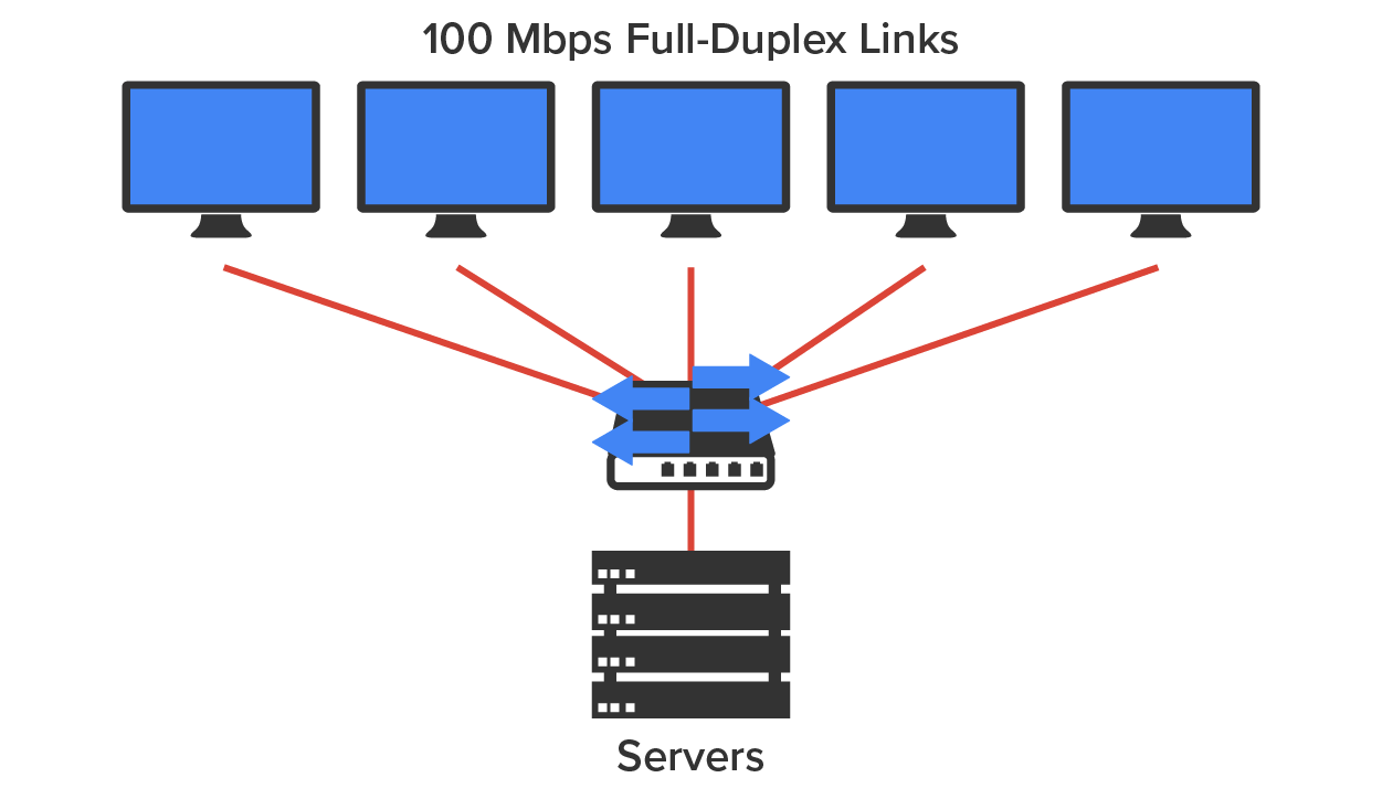
Switches create private, dedicated collision domains and provide independent bandwidth on each port, unlike hubs. The diagram below shows five hosts connected to a switch. Unlike with a hub, each host has full-duplex, 100 Mbps of dedicated communication to the server.
What makes Layer 2 switching so efficient is that no modification to the data packet takes place. The device reads only the frame encapsulating the packet, which makes the switching process considerably faster and less error-prone than Layer 3 routing processes.
Layer 2 switching increases the bandwidth for each user because each port on the switch is its own collision domain.
Switched networks break up collision domains, but remember that the network is really still one big broadcast domain. Neither Layer 2 switches nor bridges break up broadcast domains, which not only limits your network’s size and growth potential but can also reduce its overall performance!
Broadcasts and multicasts along with the slow convergence time of spanning trees—network protocols that build a loop-free logical topology for Ethernet networks—can impact performance as your network grows. These are the major reasons Layer 2 switched networks need Layer 3 routers to facilitate connectivity between different networks.
We will discuss address learning and forward/filter decisions in this tutorial.
Address Learning
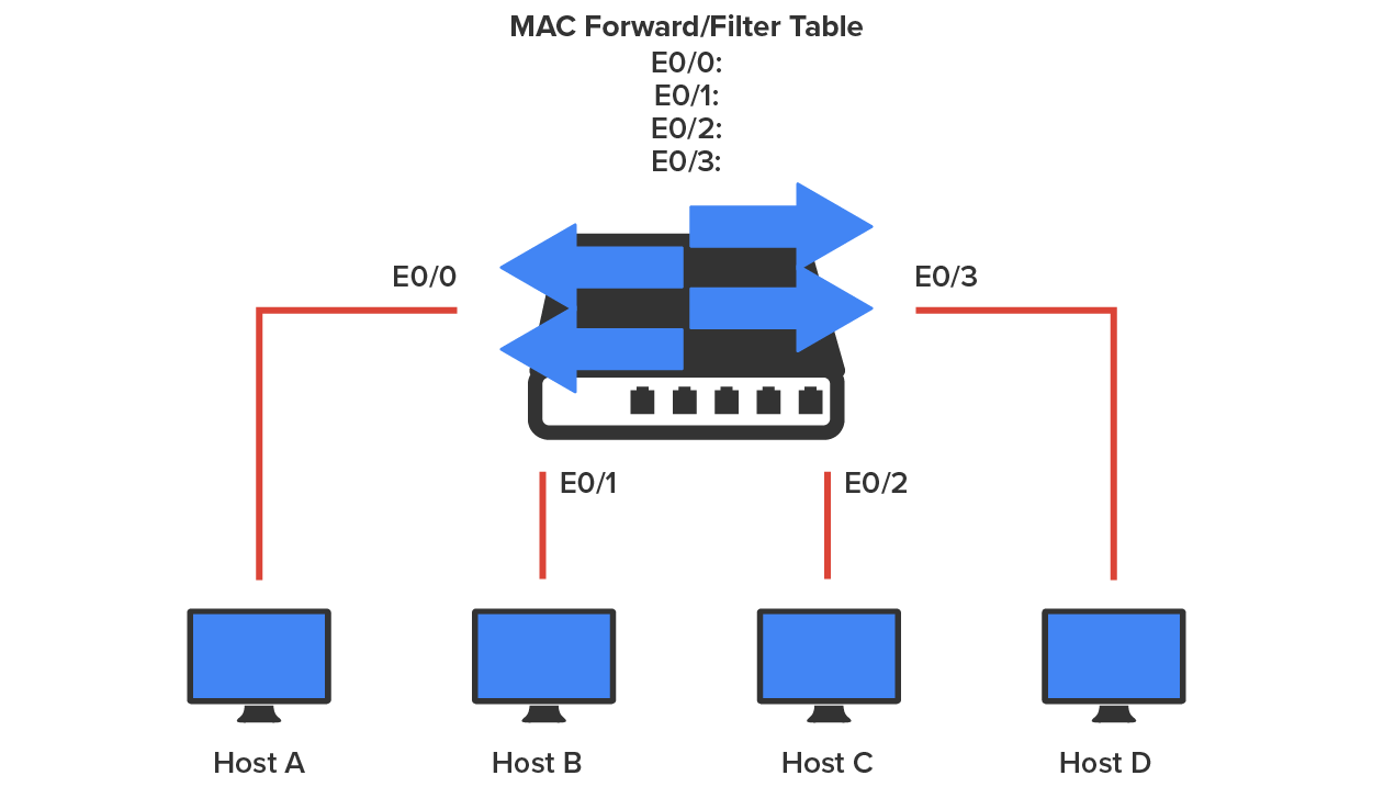
Layer 2 switches and bridges are capable of address learning; that is, they remember the source hardware address of each frame received on an interface (switch port) and enter this information into a MAC database known as a forward/filter table. When a switch is initially powered on, the MAC forward/filter table is empty, as shown in the diagram below.
When a device transmits and an interface receives a frame, the switch places the frame’s source address in the MAC forward/filter table, which allows it to remember the interface on which the sending device is located. The switch then has no choice but to flood the network with this frame out of every port except the source port because it has no idea where the destination device is actually located.
If a device answers this flooded frame and sends a frame back, then the switch will take the source address from that frame and place that MAC address in its database as well, thereby associating the newly discovered address with the interface that received the frame.
Because the switch now has both of the relevant MAC addresses in its filtering table, the two devices can make a point-to-point connection. The switch doesn’t need to flood the frame as it did the first time because, now, the frames can and will be forwarded only between the two devices recorded in the table. This is exactly the thing that makes Layer 2 switches better than hubs because, in a hub network, all frames are forwarded out of all ports every time. The diagram below shows the processes involved in building a MAC database.
EXAMPLE
In the figure below, you can see four hosts attached to a switch. When the switch is powered on, it has nothing in its MAC address forward/filter table. However, when the hosts start communicating, the switch places the source hardware address of each frame in the table along with the port that the frame’s address corresponds to.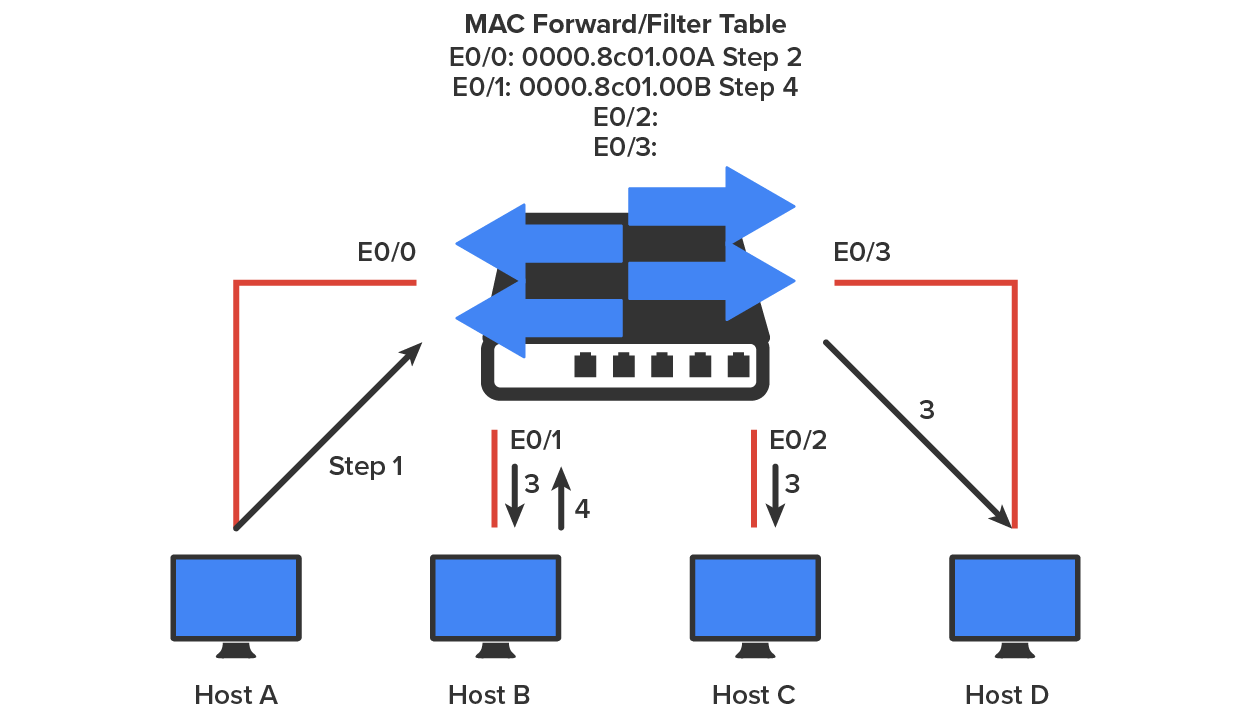
If Host A and Host B do not communicate to the switch again within a certain amount of time, the switch will flush their entries from the database to keep it as current as possible.
Forward/Filter Decisions
When a frame arrives at a switch interface, the destination hardware address is compared to the forward/filter MAC database, and the switch makes a forward/filter decision. In other words, if the destination hardware address is known (listed in the database), the frame is only sent out to the specified exit interface. The switch will not transmit the frame out of any interface except the destination interface. Not transmitting the frame preserves bandwidth on the other network segments and is called frame filtering.
In the diagram below, you can see Host A sending a data frame to Host D. What will the switch do when it receives the frame from Host A?
If you answered that because Host A’s MAC address is not in the forward/filter table, the switch will add the source address and port to the MAC address table and then forward the frame to Host D, you’re halfway there. If you also came back with, “If Host D’s MAC address were not in the forward/filter table, the switch would have flooded the frame out of all ports except for port Fa0/3,” then congratulations—you nailed it!
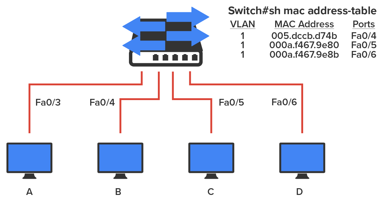
Let’s take a look at the output of a “show mac address-table” command as seen from a Cisco Catalyst switch. (The MAC address table works pretty much exactly the same on all brands of switches.)
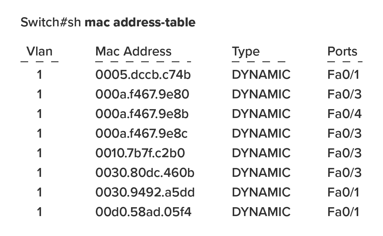
Now, suppose the preceding switch received a frame with the following MAC addresses:
Source MAC: 0005.dccb.d74b
Destination MAC: 000a.f467.9e8c
Now that you can see the MAC address table and how switches add hosts’ addresses to the forward/filter table, how do you stop switching loops if you have multiple links between switches? Let’s talk about this possible problem in more detail.
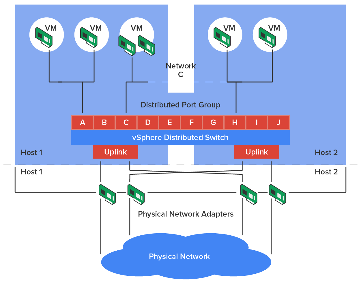
In a virtual environment such as those you might find in many of today’s data centers, not only are virtual servers used in place of physical servers, but virtual switches (software based) are used to provide connectivity between the virtual systems. These virtual servers reside on physical servers that are called hosts (but in a different context from network hosts). The virtual switches can be connected to a physical switch to enable access to the virtual servers from the outside world.
One of the unique features of these virtual switches is the ability of the switches to span multiple physical hosts. When this is done, the switch is called a distributed switch. This provides connectivity between virtual servers that are located on different hosts, as shown in the diagram below.
Source: This content and supplemental material has been adapted from CompTIA Network+ Study Guide: Exam N10-007, 4th Edition. Source Lammle: CompTIA Network+ Study Guide: Exam N10-007, 4th Edition - Instructor Companion Site (wiley.com)