Table of Contents |
A modem (modulator-demodulator) is a device that modulates an analog carrier signal to encode digital information and demodulates the signal to decode the transmitted information. The photograph below shows a current analog modem that can be used in today’s networks, albeit with slow throughput.
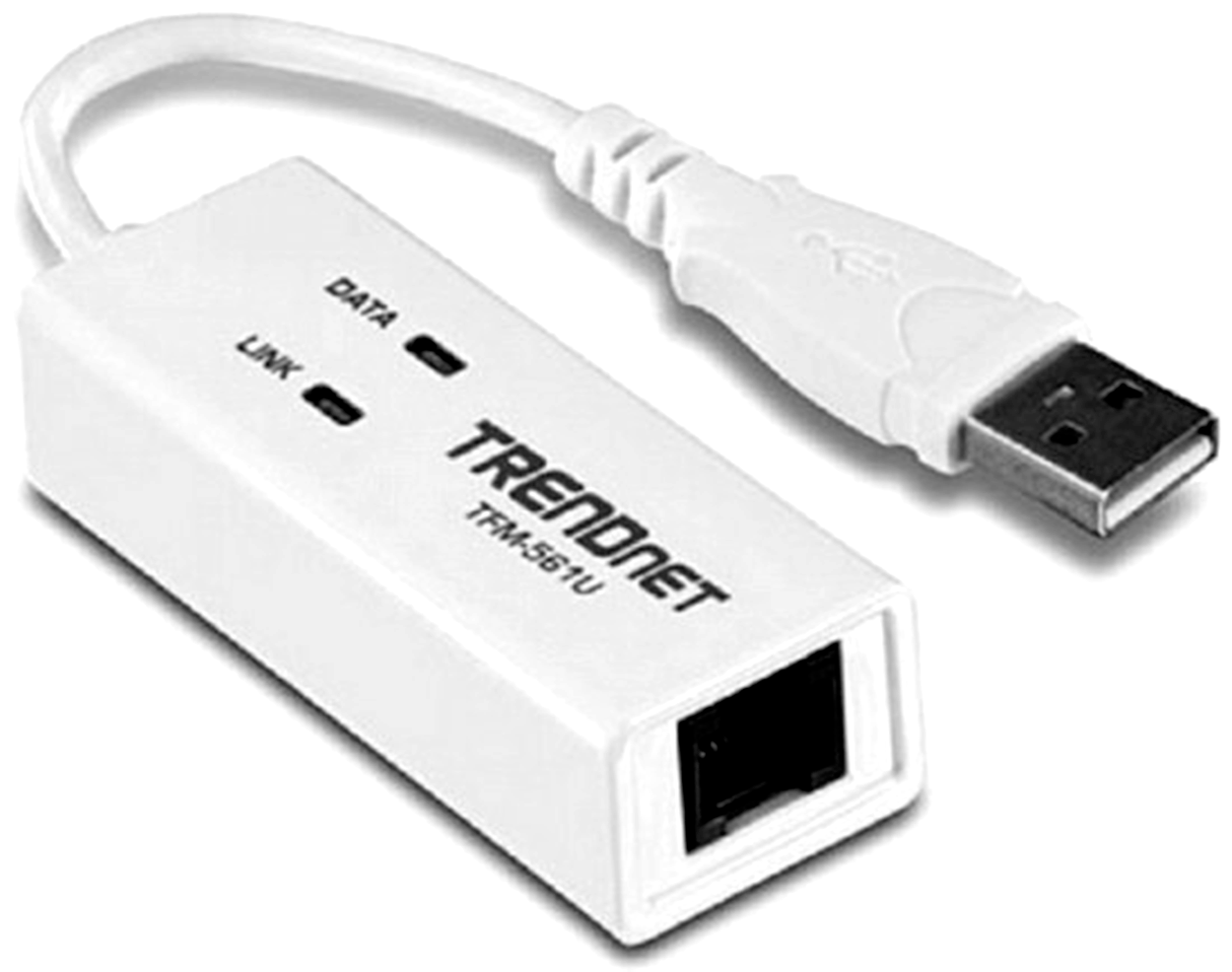
The purpose of an analog modem is to encode digital data as analog waveforms (sounds) that can be transmitted easily via phone lines, and then decode the analog data at the other end to reconstitute the original digital data. An internal modem provides an RJ-11 jack to connect to a standard telephone jack in a home or business; an external modem, like the one shown above, connects to a USB port of the computer, and a phone line runs from the RJ-11 jack on the modem to the corresponding wall jack. The analog modem operates at Layer 1.
Packet shaping (also known as traffic shaping) is a network traffic management technique that delays some or all packets to bring them into compliance with an enterprise’s requirements. The photograph below shows a dedicated packet shaper appliance.
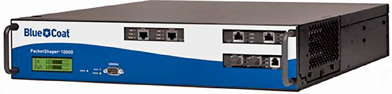
This process is used to optimize or guarantee performance, reduce latency, and/or increase usable bandwidth for some kinds of packets by delaying other kinds, for example, prioritizing voice calls over large file transfers.
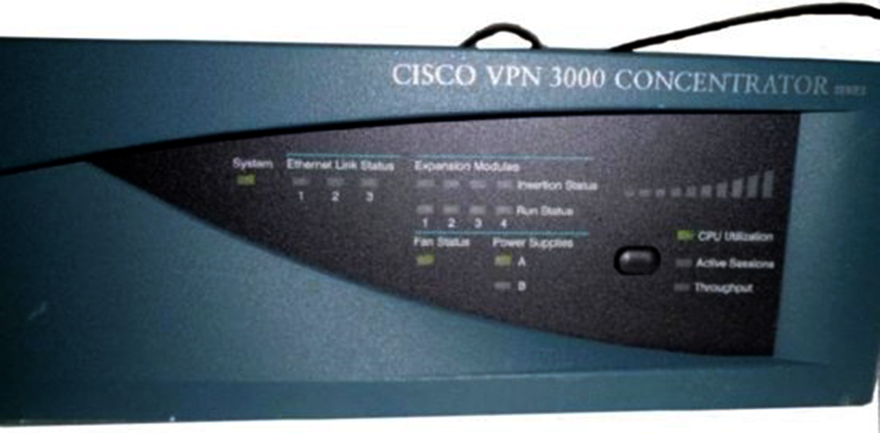
A VPN concentrator is a device that accepts multiple virtual private networking (VPN) connections from remote locations. Although this function can be performed by a router or server, there are performance benefits to be derived from dedicating a device to this, which is shown below.
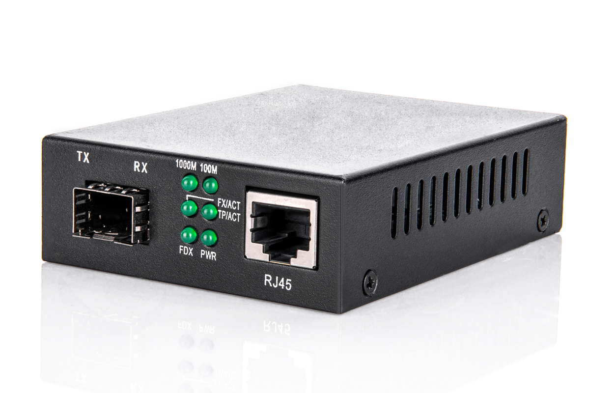
Media converters are used to convert from one type of cabling to another type. This might be required to convert from one type of fiber to another or from Ethernet to fiber, for example. The image below shows an Ethernet-to-fiber conversion box. Media converters operate at Layer 1.
A private branch exchange (PBX) is a private telephone switch that resides on the customer's premises. It has a direct connection to the telecommunication provider’s switch. It performs call routing within the internal phone system. This is how a company can have two “outside” lines but 50 internal phones. The call comes in on one of the two outside lines, and the PBX routes it to the proper extension. Sometimes, the system converts analog to digital but not always.
A VoIP PBX is one that switches calls between VoIP (voice-over Internet Protocol or IP) users on local lines while allowing all users to share a certain number of external phone lines. The typical IP PBX can also switch calls between a VoIP user and a traditional telephone user, or between two traditional telephone users, in the same way that a conventional PBX does.
A VoIP Gateway (Voice-over IP Gateway) is a network device that helps to convert voice and fax calls between an IP network and a Public Switched Telephone Network (PSTN) in real time. A VoIP gateway can typically support at least two high-speed T1/E1 digital channels. Most VoIP gateways feature at least one Ethernet and telephone port.
VoIP endpoints are desktop phone systems or wireless phone systems that are part of the converged networks where data and voice traffic are now combined in today’s networks. These endpoints may also be implemented as conferencing systems in meeting rooms. There is more flexibility and freedom in the location and installation of these systems as more wireless modes of connectivity are introduced to these devices.
Next-generation firewalls (NGFWs) are a category of devices that attempt to address the traffic inspection and application awareness shortcomings of a traditional firewall without hampering the performance.
NGFWs operate at Layer 7 and are application-aware, which means they can distinguish between specific applications instead of allowing all traffic coming in via typical web ports. Moreover, they examine packets only once during the deep packet inspection phase (which is required to detect malware and anomalies).
Determining Requirements for Implementation
When implementing a SOHO network, the first thing to be done is to identify the requirements of the network and the constraints around which you must operate. This should drive your design and device choices. An example set of requirements and constraints might be as follows:
Here is a list of some of the conditions that commonly cause LAN traffic congestion:
Routers are used to connect networks together and route packets of data from one network to another. By default, routers break up a broadcast domain. The diagram below shows a router in a network that creates an internetwork and breaks up broadcast domains.
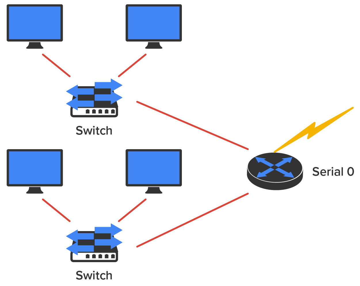
In the diagram, each host is connected to its own collision domain, and the router has created two broadcast domains.
Breaking up a broadcast domain is important because when a host or server sends a network broadcast, every device on the network must read and process that broadcast—unless you have a router. Routers do not forward broadcasts, so they discard the broadcast without forwarding it on to other networks. Even though routers are known for breaking up broadcast domains by default, it is important to remember that they break up collision domains as well.
Remember that routers can also be called Layer 3 switches. Unlike Layer 2 switches, which forward or filter frames, routers (Layer 3 switches) use logical addressing and provide what is called packet switching.
Routers can also provide packet filtering by using access control lists (ACL), and when routers connect two or more networks together and use logical addressing (IP or IPv6), this is called an internetwork. Last, routers use a routing table (a map of the internetwork) to make path selections and to forward packets to remote networks.
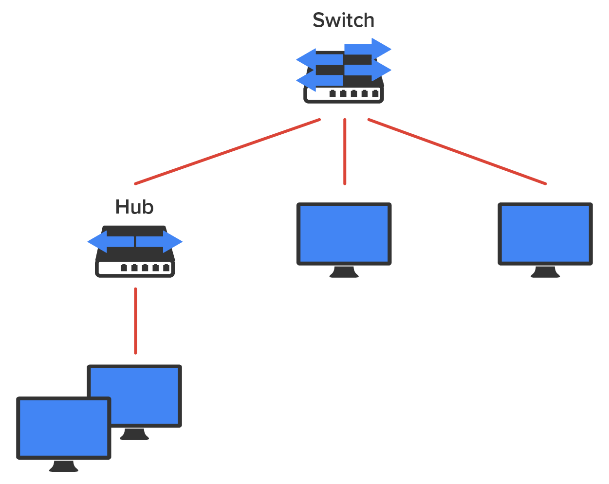
Switches do not forward packets to other networks as routers do. They only forward frames from one port to another based on MAC addresses. Switches break up collision domains, as discussed earlier in the course. A collision domain is a section of a network in which a packet collision affects all clients. At the same time, a different device tries to transmit, leading to a collision, after which both devices must retransmit, one at a time. This situation is typically found in a hub environment where each host segment connects to a hub that represents only one collision domain and only one broadcast domain. By contrast, each and every port on a switch represents its own collision domain.
The term bridging was introduced before routers and hubs were implemented, so it is common to hear people referring to switches as bridges. That is because bridges and switches both break up collision domains on a LAN. Bridges are legacy devices and are generally no longer available for purchase.
Layer 2 switching is considered a hardware-based bridging because it uses specialized hardware called an application-specific integrated circuit (ASIC). ASICs can run up to gigabit speeds with very low latency rates. Latency is the time measured from when a frame enters a port to when it exits it.
Bridges and switches read each frame as it passes through the network. The Layer 2 device then puts the source hardware address in a filter table and keeps track of which port the frame was received on. This information, which is logged in the filter table of the bridge or switch, is what helps the bridge or switch determine the sending device’s location.
The diagram below shows a switch in an internetwork.
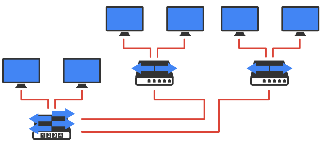
Layer 3 machines (such as routers) need to locate specific networks, whereas Layer 2 machines (switches and bridges) need to eventually locate specific devices. So, networks are to routers as individual devices are to switches and bridges. And routing tables that “map” the internetwork are for routers as filter tables that “map” individual devices are for switches and bridges.
After a filter table is built on the Layer 2 device, the device will forward frames only to the segment where the destination hardware address is located. If the destination device is on the same segment as the frame, the Layer 2 device will block the frame from going to any other segments. If the destination is on a different segment, the frame can be transmitted only to that segment. This is called transparent bridging.
When a switch interface receives a frame with a destination hardware address that is not found in the device’s filter table, it will forward the frame to all connected segments. If the unknown device that was sent the frame replies to this forwarding action, the switch updates its filter table regarding that device’s location. But in the event that the destination address of the transmitting frame is a broadcast address, the switch will forward all broadcasts to every connected segment by default.
All devices that the broadcast is forwarded to are considered to be in the same broadcast domain. This can be a problem.
The biggest benefit of using switches instead of hubs in your internetwork is that each switch port is actually its own collision domain. (Conversely, a hub creates one large collision domain.) But a switch cannot break up broadcast domains. They will typically simply forward all broadcasts instead.
Another benefit of LAN switching over hub-centered implementations is that each device on every segment plugged into a switch can transmit simultaneously, while hubs allow only one device per network segment to communicate at a time.
Source: This content and supplemental material has been adapted from CompTIA Network+ Study Guide: Exam N10-007, 4th Edition. Source Lammle: CompTIA Network+ Study Guide: Exam N10-007, 4th Edition - Instructor Companion Site (wiley.com)