In this lesson, you will learn about the basics of routing.
Specifically, this lesson will cover the following:
1. Routing Basics
In IT, routing essentially refers to the process of taking a packet from one device and sending it through the network to another device on a different network. Routers don’t really care about hosts—they care only about networks and the best path to each network. The logical network address of the destination host is used to get packets to a network through a routed network, and then the hardware address of the host is used to deliver the packet from a router to the correct destination host.
If your network has no routers, then you can only communicate with devices on your local area network. But if you do have them, they’re there to route traffic to all the networks in your internetwork.
-
To be capable of routing packets, a router must know at least the following:
- The destination network address
- Neighboring routers from which it can learn about remote networks
- Possible routes to all remote networks
- The best route to each remote network
- A way to maintain and verify routing information
The router will learn about remote networks from neighboring routers or from an administrator. The router then builds a routing table (a map of the internetwork) that describes how to find the remote networks. If a network is directly connected, then the router already knows how to get to it.
If a network isn’t directly connected to the router, the router must use one of two ways to learn how to get to it. One way is called static routing, which can be a ton of work because it requires someone manually entering all network locations into the routing table. The other way is dynamic routing.
-
In
dynamic routing, a protocol on one router communicates with the same protocol running on neighboring routers. The routers then update each other about all the networks they know about and place this information into the routing table. If a change occurs in the network, the dynamic routing protocols automatically inform all routers about the event. If static routing is used, the administrator is responsible for updating all changes manually into all routers.
Before we jump into the IP routing process, let’s take a look at a simple example that demonstrates how a router uses the routing table to route packets out of an interface. We’ll be going into a more detailed study of this process shortly.
The diagram below shows a simple two-router network. Lab_A has one serial interface and three LAN interfaces.
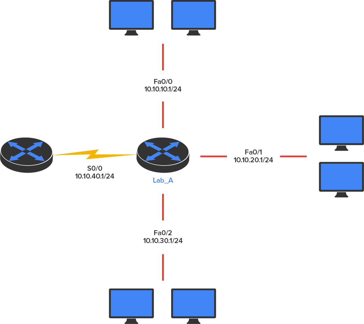
Looking at the diagram above, can you figure out which interface Lab_A will use to forward an IP datagram to a host with an IP address of 10.10.10.10?
By using the Cisco IOS command “show ip route”, you can see the routing table (map of the internetwork) that router Lab_A will use to make all forwarding decisions:
Router_A#show ip route
Gateway of last resort is not set
C 10.10.10.0/24 is directly connected, FastEthernet0/0
C 10.10.20.0/24 is directly connected, FastEthernet0/1
C 10.10.30.0/24 is directly connected, FastEthernet0/2
C 10.10.40.0/24 is directly connected, Serial 0/0
The C in the routing table output means that the networks listed are “directly connected,” and until we add a routing protocol—something like Routing Information Protocol (RIP), Enhanced Interior Gateway Protocol (EIGRP), and so on—to the routers in our internetwork, or use static routes, we’ll have only directly connected networks in our routing table.
So, let’s get back to the original question: By looking at the figure and the output of the routing table, can you tell what Lab_A will do with a received packet that has a destination IP address of 10.10.10.10? If you answered, “The router will packet-switch the packet to interface FastEthernet 0/0, and this interface will then frame the packet and send it out on the network segment,” you’re right.
-
EXAMPLE
Based on the output of the next routing table, which interface will a packet with a destination address of 10.10.10.14 be forwarded to?
Router_A#sh ip route
Gateway of last resort is not set
C 10.10.10.16/28 is directly connected, FastEthernet0/0
C 10.10.10.8/29 is directly connected, FastEthernet0/1
C 10.10.10.4/30 is directly connected, FastEthernet0/2
C 10.10.10.0/30 is directly connected, Serial 0/0
First, you can see that the network is subnetted and that each interface has a different mask. 10.10.10.14 would be a host in the 10.10.10.8/29 subnet connected to the FastEthernet 0/1 interface. One way to quickly calculate this is to write out the binary for /29 to see that the value of the last borrowed host bit is 8. This means that the subnet IDs will increment by 8, so the next subnet ID after 10.10.10.8/29 is 10.10.10.16/29, which leaves the addresses 10.10.10.9 through 10.10.10.14 as host addresses, and 10.10.10.15 is the broadcast address for the 10.10.10.8 subnet.
-
- Routing
- A method of finding paths from origins to destinations in a network such as the Internet, along which information can be passed.
- Routing Table
- A table of networks that a router is connected to and/or aware of.
- Static Routing
- Routing via unchanging paths to a destination network.
- Dynamic Routing
- Routing via changing paths to a destination network.
2. The IP Routing Process
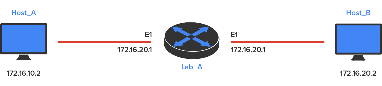
The IP routing process is actually pretty simple, and it doesn’t change regardless of the size of your network. What happens when Host_A wants to communicate with Host_B on a different network, as shown in the diagram below? To answer that question, let’s break down the process into steps
-
- A packet is created on the host
- Internet Control Message Protocol (ICMP) creates an echo request payload.
- ICMP hands that payload to IP, which then creates a packet.
- After the packet is created, IP determines whether the destination IP address is on the local network or a remote one.
- Because IP has discovered that this is a remote request, the packet needs to be sent to the default gateway, which is the IP address of the local router interface, so the packet can be routed to the correct remote network.
- The default gateway of host 172.16.10.2 (Host_A) is configured to 172.16.10.1. For this packet to be sent to the default gateway, the hardware address of the router’s interface Ethernet 0 (configured with the IP address of 172.16.10.1) must be known. Why? So the packet can be handed down to the data link layer, framed, and sent to the router’s interface that’s connected to the 172.16.10.0 network. Because hosts only communicate via hardware addresses on the local LAN, it’s important to recognize that for Host_A to communicate with Host_B, it has to send packets to the Media Access Control (MAC) address of the default gateway on the local network.
- The Address Resolution Protocol (ARP) cache of the host is checked to see whether the IP address of the default gateway has already been resolved to a hardware address. If it has, the packet is then free to be handed to the data link layer for framing. If the hardware address isn’t already in the ARP cache of the host, an ARP broadcast is sent out onto the local network to search for the hardware address of 172.16.10.1. The router responds to that request and provides the hardware address of Ethernet 0, and the host caches this address.
- After the packet and destination hardware address have been handed to the data link layer, Ethernet generates a frame that encapsulates the packet with control information. It contains Host_A’s hardware (MAC) address and the hardware-destination address of the default gateway. It does not include the remote host’s MAC address—remember that because it’s important!
- When the frame is completed, it’s handed down to the physical layer to be placed onto the physical medium one bit at a time. In this example, the physical medium is twisted-pair wire. The router receives the frame.
- Every device within the collision domain receives these bits and builds the frame. They each run a Cyclic Redundancy Check (CRC) and check the answer in the Frame Check Sequence (FCS) field. If the answers don’t match, the frame is discarded. But if the CRC matches, then the hardware-destination address is checked to see if it matches, too (in this example, it’s the router’s interface, Ethernet 0).
- The packet is pulled from the frame, and what is left of the frame is discarded. The packet is then handed to the protocol listed in the Ether-Type field, which is typically IP.
- IP receives the packet and checks the IP destination address. Because the packet’s destination address doesn’t match any of the addresses configured on the receiving router’s interfaces, the router will look up the destination IP network address in its routing table.
- The routing table must have an entry for the network 172.16.20.0 or the packet will be discarded immediately and an ICMP message will be sent back to the originating device with a destination unreachable message.
- If the router does find an entry for the destination network in its table, the packet is switched to the exit interface—in this example, interface Ethernet 1. The following output displays the Lab_A router’s routing table. The C means “directly connected.” No routing protocols are needed in this network because all networks (all two of them) are directly connected:
- Lab_A>sh ip route
Codes:C - connected, S - static,I - IGRP, R - RIP,M - mobile, B -
BGP, D - EIGRP, EX - EIGRP external,0 - OSPF,IA - OSPF inter
area, N1 - OSPF NSSA external type 1, N2 - OSPF NSSA external type 2, El - OSPF external
type 1, E2 - OSPF external type 2, E - EGP, i - IS-IS, L1 - IS-IS level-1, L2 - IS-IS level-2, ia
- IS-IS intearea * - candidate default, u - per-user static route, o - ODR P - periodic downloaded static route
- Gateway of last resort is not set
172.16.0.0/24 is subnetted, 2 subnets
C 172.16.10.0 is directly connected Ethernet0
C 172.16.20.0 is directly connected Ethernet1

- The router sends the packet to the Ethernet 1 buffer.
- Now that the packet is in the Ethernet 1 buffer, IP needs to know the hardware address of the destination host and first checks the ARP cache. If the hardware address of Host_B has already been resolved and is in the router’s ARP cache, then the packet and the hardware address are handed down to the data link layer to be framed.
- The router may find the 172.16.10.2 (Host_A) and 172.16.20.2 (Host_B) hardware addresses in its ARP cache. Cisco routers will keep an entry in the ARP table for four hours. But if the hardware address hasn’t already been resolved, the router then sends an ARP request out E1 looking for the hardware address of 172.16.20.2. Host_B responds with its hardware address, and the packet and hardware-destination address are both sent to the data link layer for framing.
- The data link layer creates a frame with the destination and source hardware address, Ether-Type field, and FCS field at the end, as shown in the illustration above. The frame is handed to the physical layer to be sent out on the physical medium one bit at a time. Finally, the remote host receives the packet.
- Host_B receives the frame and immediately runs a CRC. If the result matches what’s in the FCS field, the hardware-destination address is then checked. If the host finds a match, the Ether-Type field is then checked to determine the protocol that the packet should be handed to at the network layer—IP, in this example.
- At the network layer, IP receives the packet and checks the IP destination address. Because there’s finally a match made, the Protocol field is checked to find out to where the payload should be delivered.
- The payload is handed to ICMP, which recognizes that this is an echo request. ICMP responds to this by discarding the packet immediately and generating a new payload as an echo reply. The entire routing process then begins again with Host_B transmitting the ICMP response back to Host_A.
The key point to understand is that if you had a much larger network, the process would be the same. In a really big internetwork, the packet just goes through more hops before it finds the destination host.
-
- Default Gateway
- The IP address of the local router interface.
In this lesson, you learned about routing basics. You learned the fundamentals of the IP routing process.