Table of Contents |
When network engineers design and troubleshoot networks, they think about them from two different perspectives: the physical layout and the logical layout. Understanding both perspectives is essential for grasping how networks really work.
A physical layout, or topology, is how the network is literally wired together. It’s a map showing where the cables run and where hardware, such as computers, switches, and routers, is physically located. Think of it as the architectural floor plan of the network. It shows the tangible, real-world arrangement of every piece.
A logical layout, or topology, on the other hand, describes how data flows through the network and how devices communicate with each other, regardless of their physical location. It’s the path that information takes from one computer to another. For example, you might have two computers sitting side by side in an office (their physical location), but for security reasons, the data might travel from the first computer to a router on another floor and back again before reaching the second computer. This path is the logical layout. It’s like a city’s bus route map—it shows the path of travel, not every single street along the way.
Understanding both layouts is also important for troubleshooting. If an employee cannot access the company website, the cause may be physical, such as a damaged cable or failed switch port, or logical, such as an incorrect IP address or a firewall rule blocking the connection. Network engineers need to evaluate both perspectives to find the real source of the issue.
The physical layout of a network is often designed in a specific shape, or topology. Each topology has its own strengths and weaknesses, making it suitable for different situations.
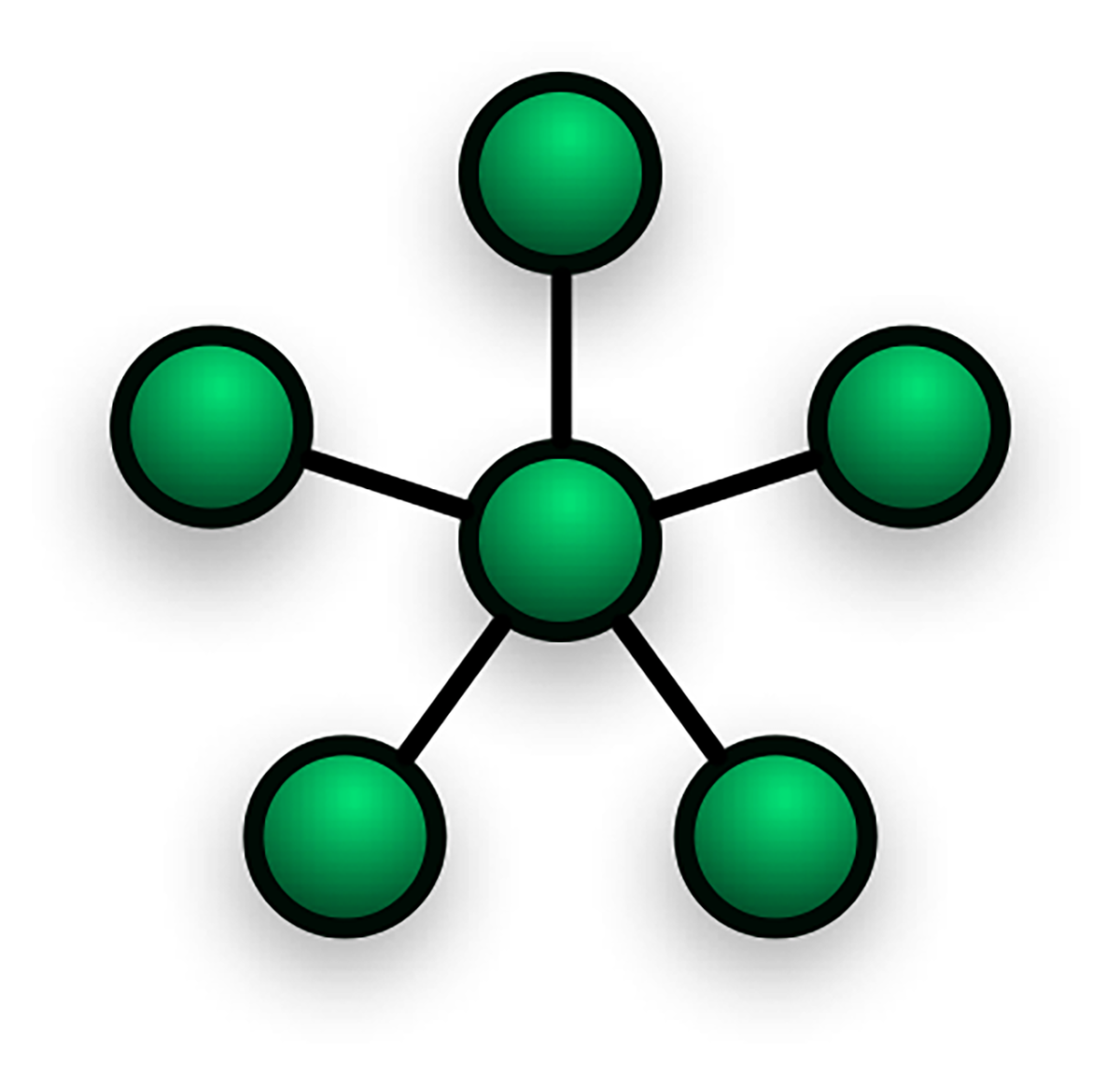
Star Topology: All devices are connected to a central piece of hardware, such as a switch or a hub. This is the most common topology in modern home and office networks. It works like a bicycle wheel—the devices are the points on the rim and the central switch is the hub in the middle, with a spoke connecting each one. Star topologies are reliable because if one computer’s cable fails, the rest of the network stays online. They are also easy to expand and troubleshoot. However, the network depends entirely on the central switch, so if that device fails, the entire network goes down.
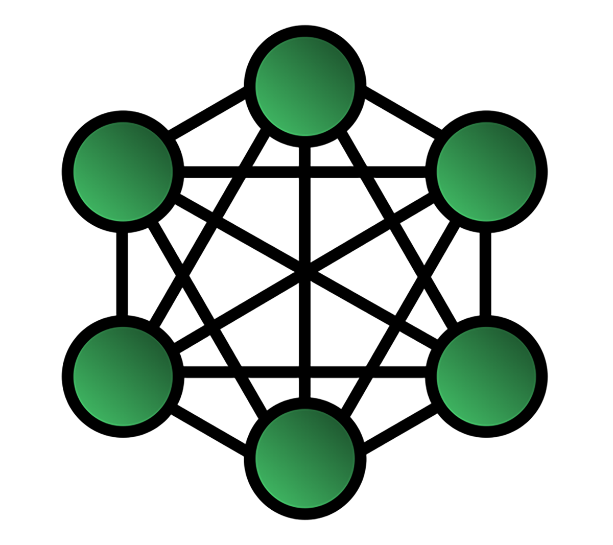
Mesh Topology: Devices are interconnected, either fully with every device connected to every other device or partially with each device connected to several others. A mesh works like a spider’s web with many different paths from one point to another. Mesh topologies are extremely reliable and redundant because if one connection fails, data can take another route. This makes them ideal for critical connections. The drawback is that they are expensive and complex to set up because of the large number of connections required.
Hybrid Topology: A combination of two or more topologies. For example, a company might use a star topology in each department and then connect those departmental switches with a central backbone, creating a star-bus hybrid. This flexibility is equivalent to mixing different road systems in a city to handle local traffic while still connecting to major highways. Hybrid topologies are highly flexible and scalable because they can be tailored to specific needs. At the same time, they can be harder to manage and more expensive than a single topology.
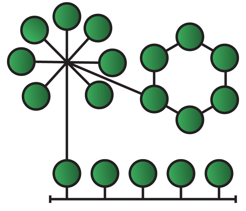
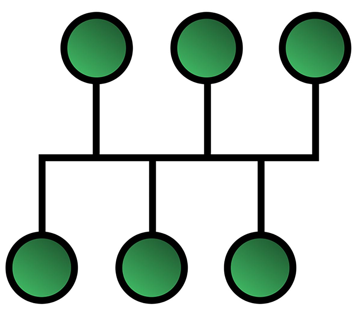
Bus Topology: A legacy design where all devices connect to a single main cable called a bus or backbone. It was cheap and easy to set up, but like an old string of holiday lights, if the main cable failed, the entire network stopped working.
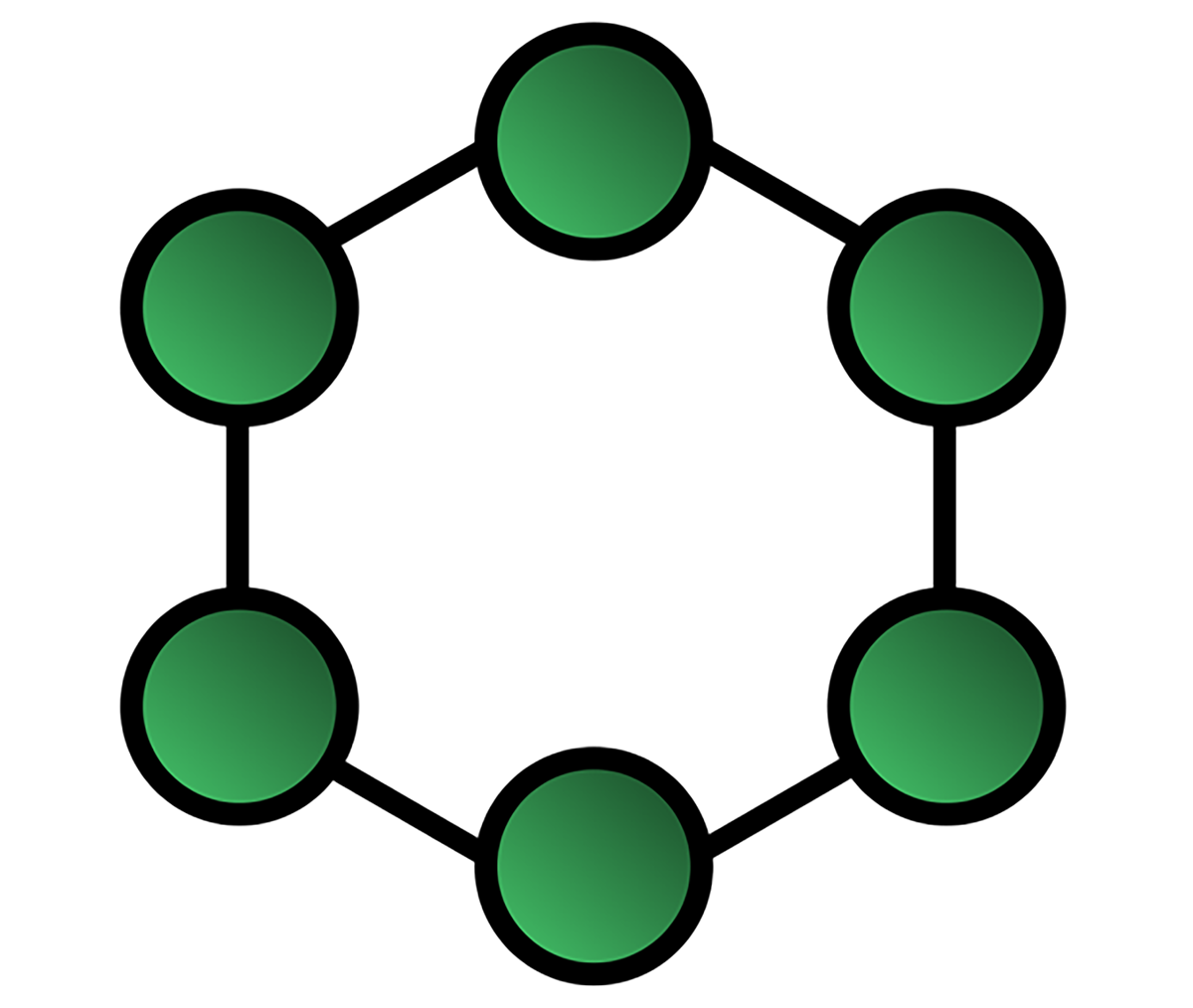
Ring Topology: Another legacy design where devices are connected in a circle and data passes from one device to the next. It functioned like a relay race, with each device passing information along the ring. While orderly, the design was vulnerable because a single break could stop the entire flow of data.
Data does not just flow through cables on its own. Network devices are specialized pieces of hardware that move data around networks. Each type serves a specific purpose in managing how information flows between devices.
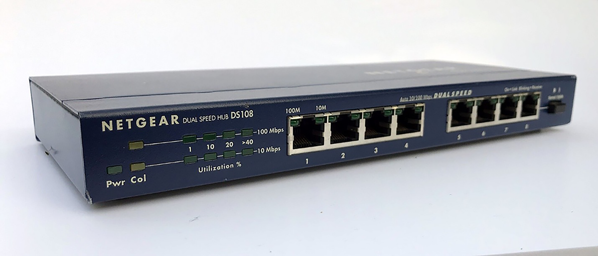
A hub is a basic device that connects multiple computers in a network. When it receives data from one device, it does not know the destination, so it broadcasts the data to every device connected to it. This is like a loudspeaker in a room that shouts every message to everyone, leaving each person to decide whether the message is for them. Because this creates unnecessary traffic and inefficiency, hubs are now considered obsolete and have largely been replaced by switches.
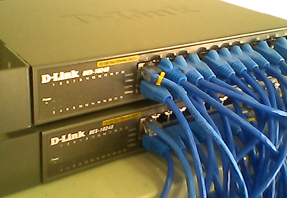
A switch is a more advanced device that took the hub’s place. When it receives data, it reads the destination address, called a MAC address, and forwards the data only to the intended device. It works like a smart mail room sorter that reads the office number on each letter and places it directly into the correct mailbox instead of shouting it to the entire building. Switches make networks much faster and are more efficient than hubs.
A router connects different networks together. For example, your home network is one network, and the internet is another. A router links the two, allowing devices on your home network to connect with the outside world and send and receive information. Routers use IP addresses to determine the best path for data to travel. A router acts like a GPS for your data by looking at the destination address and calculating the most efficient route for it to reach its destination.
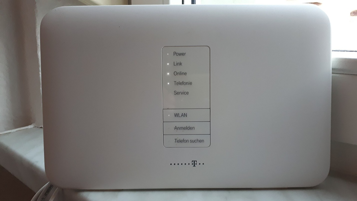
A wireless access point (WAP) allows computers and other devices to connect to a wired network using Wi-Fi. It serves as a bridge between wireless and wired systems. A WAP is like a radio tower that broadcasts a signal your devices can tune into, giving laptops, phones, and tablets access to the network without physical cables.
Beyond core devices like switches and routers, networks also depend on additional components that support organization, security, and performance. These supporting tools may not always be visible to everyday users, but they play an essential role in keeping a network stable, secure, and easy to manage.
A patch panel is used in large networks where cables from wall jacks across a building run to a central wiring closet. Instead of plugging directly into a switch, the cables terminate at the patch panel. This device acts as an organizational board of ports, making it easy to connect and disconnect short, manageable patch cables to the switch. Patch panels keep wiring closets neat, organized, and easier to maintain.
A firewall is a network security device that acts as a barrier between a trusted internal network and an untrusted external network, such as the internet. It inspects all incoming and outgoing traffic and decides whether to allow or block it based on security rules. Firewalls can be dedicated hardware devices or software running on a computer or server.
A load balancer is used by busy websites and applications that rely on many servers working together. It sits in front of these servers and distributes incoming traffic among them so that no single server becomes overloaded. This keeps services fast, stable, and responsive for users, even under heavy demand.
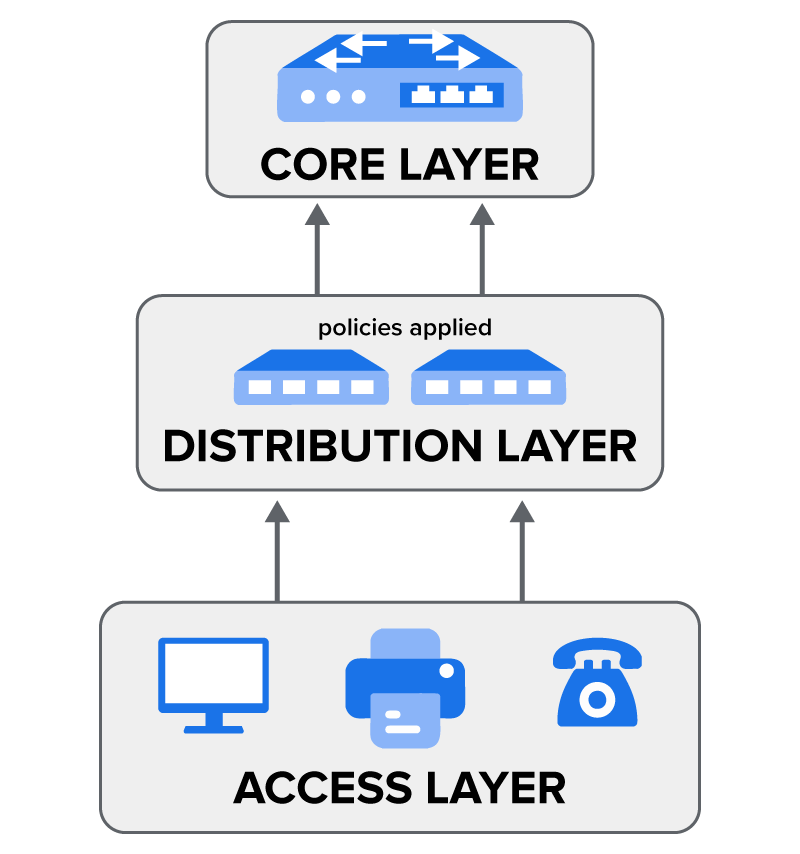
A small office network might function with just one switch and a router. Larger organizations, however, face more complex challenges. A university campus or a corporation with multiple buildings may need to connect thousands of devices, enforce security policies, and keep traffic moving efficiently between locations. To handle this scale, network engineers often use a layered approach called the three-tier hierarchical model.
An Access Layer is where end devices such as computers, phones, and printers connect to the network. This layer focuses on providing reliable connectivity and port security, ensuring that only authorized devices can plug in.
A Distribution Layer serves as the middleman. It collects traffic from the Access Layer switches and forwards it to the core. This layer is also where many policies are applied, such as filtering traffic or controlling which departments can communicate with one another.
A Core Layer is the superfast backbone of the network. Its job is to switch and route traffic between the Distribution Layer devices as quickly as possible. The core is designed for speed and reliability, so engineers avoid placing policies here that could slow it down.
Networks are never static. As organizations grow, new employees join, new services are added, and more data flows through the system. If a network is not designed with future needs in mind, it can quickly become a bottleneck or even fail during critical operations. Two principles help prevent this: redundancy and scalability.
Redundancy is the practice of adding duplicate components to a network to ensure that it keeps running even if one part fails. It’s like having a spare tire in your car. You hope you never need it, but if you get a flat, you aren’t stranded.
EXAMPLE
A business might use two core routers. If one fails, traffic is automatically rerouted through the second one with no downtime. This is critical for organizations that can’t afford to have their network go down.Scalability is the ability of a network to grow and handle increased demand without needing a complete redesign. It’s like building a house with a foundation that’s strong enough to support a second floor later on.
EXAMPLE
When buying a switch for the Access Layer, a network administrator might choose a 48-port switch even if they only need 30 ports today. The extra ports allow them to easily add more devices in the future without buying new hardware.Source: THIS TUTORIAL WAS AUTHORED BY SOPHIA LEARNING. PLEASE SEE OUR TERMS OF USE.