Table of Contents |
Redundant links between switches are often implemented because they help prevent network failures in the event that one link stops working. Even though redundant links can be extremely helpful in providing network availability, they can cause problems. This is because frames can be flooded down all redundant links simultaneously, creating loops that bring down a network.
Here are some of the potential problems you might encounter in loop avoidance.
EXAMPLE
If no loop avoidance schemes are put in place, the switches will flood broadcasts endlessly throughout the network. This is sometimes referred to as a broadcast storm. The diagram below illustrates how a broadcast can be propagated repeatedly throughout the network. Notice how a frame is recirculated in an endless loop through the internetwork’s physical network media.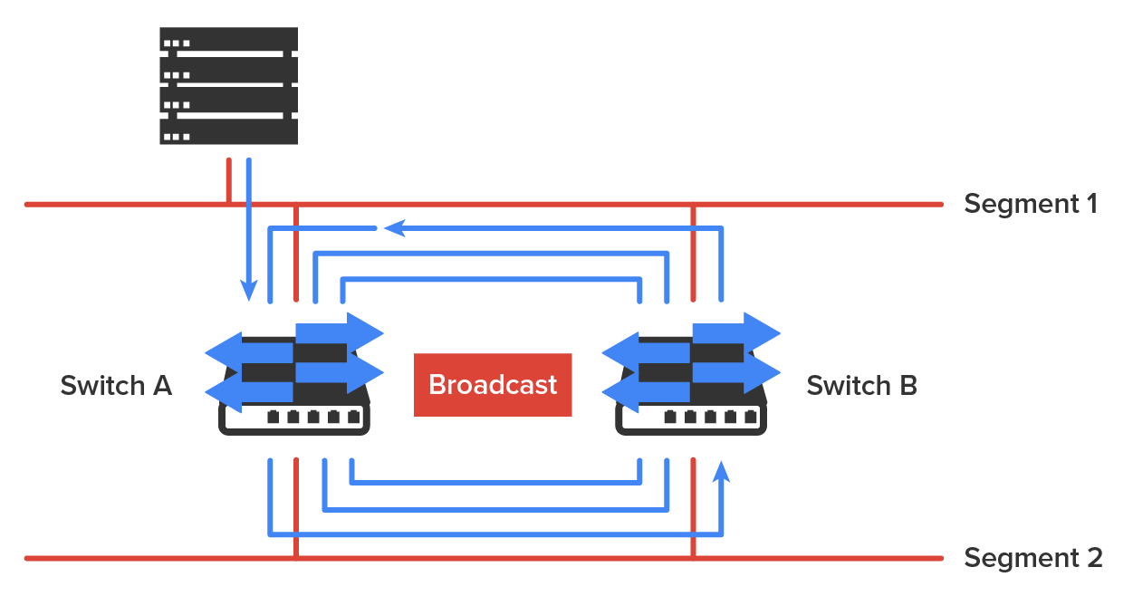
EXAMPLE
What you see in the diagram below is that a device can receive multiple copies of the same frame because that frame can arrive from different segments at the same time. Notice how a whole bunch of frames can arrive from multiple segments simultaneously. The server in the figure sends a unicast frame to another device connected to Segment 1. Because it’s a unicast frame, Switch A receives and forwards the frame, and Switch B provides and forwards the unicast. This is bad because it means that the destination device on Segment 1 receives that unicast frame twice, causing additional overhead on the network.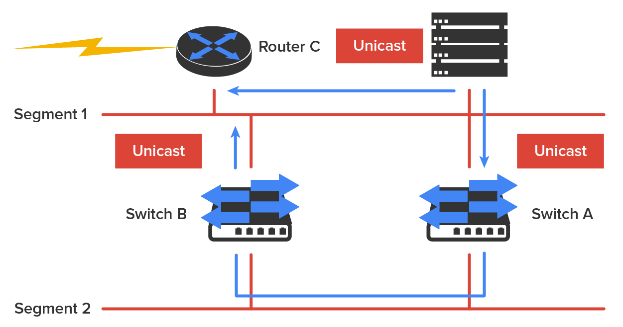
EXAMPLE
The MAC address forward/filter table could be totally confused about the device’s location because the switch can receive the frame from more than one link. Worse, the bewildered switch could get so caught up in constantly updating the MAC filter table with source hardware address locations that it might fail to forward a frame! This is called thrashing the MAC table.EXAMPLE
One of the worst things that can happen is having multiple loops propagating throughout a network. This means that you end up with loops occurring within other loops, and if a broadcast storm happened at the same time, the network wouldn’t be able to perform frame switching at all.All of these problems must be avoided. That’s where the spanning tree protocol (STP) comes into play. It was developed to solve each and every one of the problems described above.
The spanning tree protocol (STP) enables loop-free connectivity in switched networks that use redundant links. Most switches run the IEEE 802.1D version of STP by default, but there is a new industry standard called 802.1w, which is faster.
STP’s main task is to stop network loops from occurring on your Layer 2 network. It achieves this by monitoring the network to find all links and making sure that no loops occur by shutting down any redundant ones. STP uses the spanning-tree algorithm (STA) to first create a topology database and then identify and block redundant links. With STP running, frames will be forwarded only on the unblocked STP-picked links. Switches transmit special frames called Bridge Protocol Data Units (BPDUs) out of all ports so that all links between switches can be found.
STP is necessary in networks such as the one shown in the diagram below.
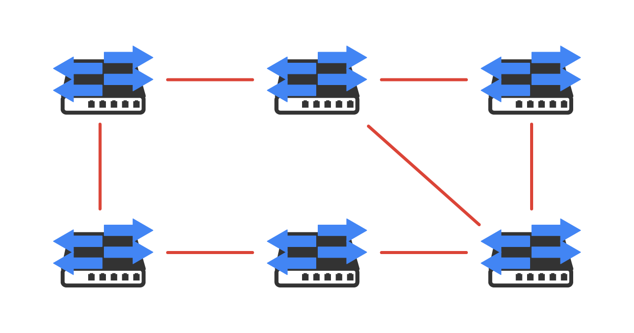
In the diagram above, you see a switched network with a redundant topology (switching loops). Without some type of Layer 2 mechanism to stop network loops, it would fall victim to the problems discussed previously: broadcast storms and multiple frame copies.
The ports on a bridge or switch running STP can transition through five different states:
A blocked port will not forward frames; it just listens to BPDUs and will drop all other frames. The purpose of the blocking state is to prevent the use of looped paths. All ports are in a blocking state by default when the switch is powered up.
The port listens to BPDUs to make sure no loops occur on the network before passing data frames. A port in the listening state prepares to forward data frames without populating the MAC address table.
The switch port listens to BPDUs and learns all the paths in the switched network. A port in the learning state populates the MAC address table but does not forward data frames. The forward delay is the time it takes to transition a port from listening to learning mode. It is set to 15 s by default.
If the port is still a designated or root port at the end of the learning state, it enters the forwarding state. In the forwarding state, the port sends and receives all data frames on the bridged port, which is a computer networking device that creates a single, aggregate network from multiple communication networks or network segments.
A port in the disabled state (administratively) does not participate in frame forwarding or STP. A port in the disabled state is virtually nonoperational.
A forwarding port is one that has been determined to have the lowest (best) cost to the root bridge. However, when and if the network experiences a topology change because of a failed link or when someone adds a new switch into the environment, you will find the ports on a switch in the listening and learning states.
Blocking ports is a strategy for preventing network loops. Once a switch determines the best path to the root bridge, all other redundant ports will be in blocking mode. Blocked ports can still receive BPDUs, but they do not send out any frames.
Convergence on Layer 2 devices is what happens when all the ports on bridges and switches have transitioned to either forwarding or blocking modes. This convergence process is similar to the way routers converge their routing tables when a route goes up or down.
During this phase, no data will be forwarded until the convergence event is complete. Plus, before data can begin being forwarded again, all devices must be updated. So, when STP is converging, all host data stops transmitting! Your switched network needs to be designed really well so that STP can converge quickly to reduce negative impacts on performance.
EXAMPLE
The diagram below demonstrates a really great way to design and implement your switched network so that STP converges efficiently.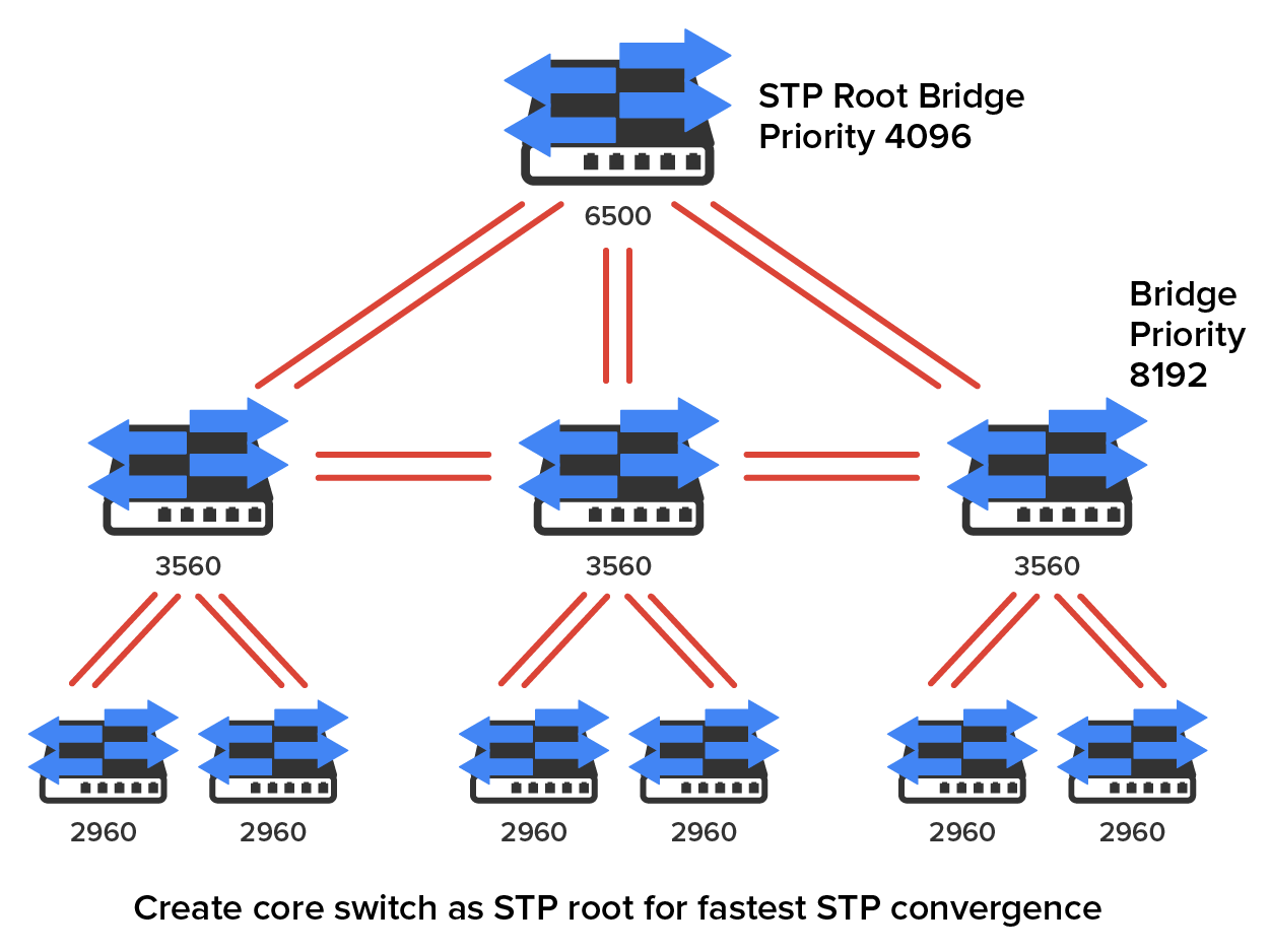
Because the typical spanning tree topology’s time to convergence from blocking to forwarding on a switch port is 50 s, it can create time-out problems on your servers or hosts when you reboot them. To address this hitch, you can disable the spanning tree on individual ports.
The Rapid Spanning Tree Protocol (RSTP) 802.1w, also known as 802.1w, enables you to have a good STP configuration running on your switched network to converge in 5 s instead of taking 50 s. RSTP was designed to be an evolution of the 802.1d standard, with a faster convergence time when a topology change occurs and backward compatibility.
The 802.1w protocol is defined in these different port states (compared to 802.1D):
Source: This content and supplemental material has been adapted from CompTIA Network+ Study Guide: Exam N10-007, 4th Edition. Source Lammle: CompTIA Network+ Study Guide: Exam N10-007, 4th Edition - Instructor Companion Site (wiley.com)