Table of Contents |
Light can behave as a particle or a wave. In this chapter, we will focus on understanding the characteristics of light waves to understand how microscopes work. This will help us use microscopes effectively because there are many types of microscopes as well as microscopy, slide preparation, and staining techniques to choose from.
The light waves that we can see (visible light) are a type of electromagnetic radiation (EMR). EMR refers to electric and magnetic fields and includes x-rays, gamma rays, and other rays that are described later in this lesson. Light waves have characteristics that are similar to other waves. These characteristics help us explain the properties of microscopy.
Several terms are used to describe the characteristics of waves, and these are illustrated in the image below. Amplitude is the height of a wave peak—as shown in image (a)—or the depth of a wave trough, whereas wavelength is the distance between one peak and the next. The waves shown in image (b) have different frequencies—or rates of vibration—which are defined as the number of wavelengths within a specified time period. The wave at the top has the lowest frequency because it has the fewest peaks per unit of time. The wave at the bottom has the highest frequency.
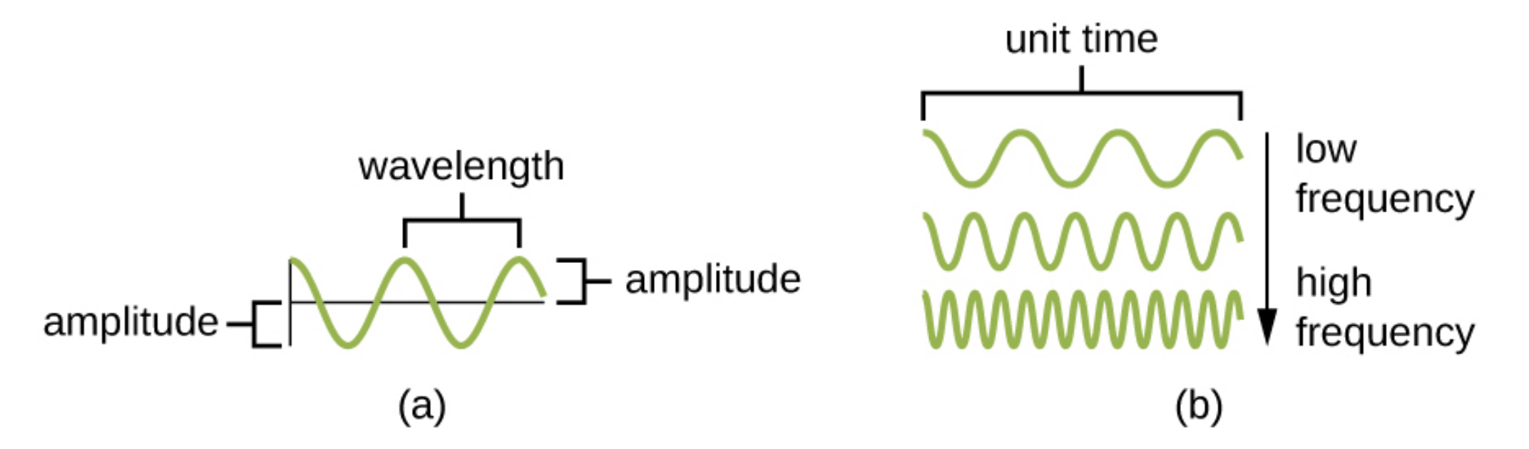
Understanding the characteristics of waves is important for understanding why different types of EMR are used in different types of microscopes. For example, waves with high energy have greater frequencies and smaller wavelengths than lower-energy waves. As you learn about the different types of microscopes, pay attention to how these characteristics affect the types of images produced.
Light can also behave like a particle. These packets of energy are called photons. It is sometimes useful to think of light as a wave, but the concept of photons can be helpful in thinking about topics such as the absorption or loss of energy. You will learn more about photons in other lessons.
The electromagnetic spectrum describes the characteristics of different forms of EMR. Alternating current (AC) circuits produce waves at the low end of the EMR spectrum. The other types of waves, listed from the lowest energy to the highest energy, are television and audio broadcasting, radar, terahertz radiation, infrared radiation, visible light, ultraviolet (UV) light, x-rays, gamma rays, and cosmic radiation.
The lowest energy EMR (AC currents) has the longest wavelengths and the lowest frequencies, whereas the highest energy EMR (cosmic radiation) has the shortest wavelengths and highest frequencies. Visible light ranges from lower-energy red light to higher-energy violet light.
Visible light appears white but can be separated into different colors of different wavelengths through processes that will be described later in this lesson.
The image below shows the electromagnetic spectrum ranging from high-frequency gamma rays to low-frequency radio waves. Visible light is the relatively small range of electromagnetic frequencies that can be sensed by the human eye. On the electromagnetic spectrum, visible light falls between UV and infrared light.

When light hits a material, it can be reflected, absorbed, or transmitted. Reflection occurs when a wave bounces off of a material. For example, a red piece of cloth may reflect red light to our eyes while absorbing other colors of light. Absorbance occurs when a material captures the energy of a light wave. In the case of glow-in-the-dark plastics, the energy from light can be absorbed and then released to produce the glow. Transmission occurs when a wave travels through a material, like light through glass. This is called transmittance. When materials allow a large proportion of light to be transmitted, they may do so because the material is thinner or more transparent.
The images below show a petri dish (a) made of transparent plastic or glass that allows the transmission of a high proportion of light. This transparency allows us to see through the sides of the dish to view the contents. Image (b) shows that a slice of an iron meteorite is opaque (i.e., it has opacity). Light is not transmitted through the material, making it impossible to see the part of the hand covered by the object.
: modification of work by Umberto Salvagnin; source (b): modification of work by “Waifer X”/Flickr.")
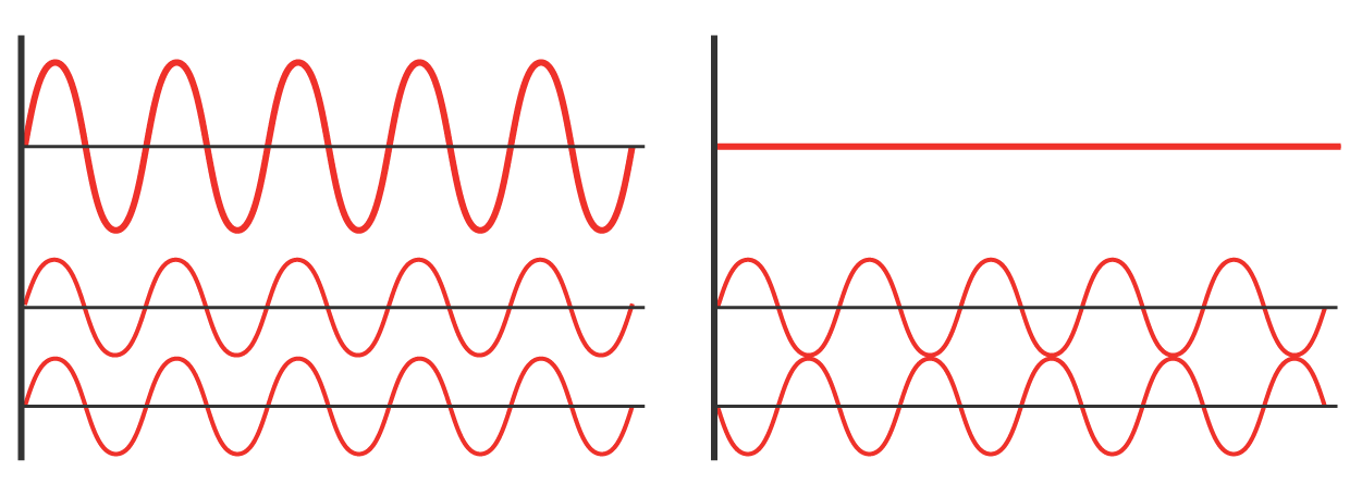
When waves such as light waves meet, they can interact. This is called interference. The figure below shows two examples of interference. On the left, two identical waves are shown that are exactly in phase with simultaneous peaks and inverse peaks. Above these waves, the wave produced by constructive interference has the same pattern of peaks and inverse peaks, but twice the amplitude. On the right, the bottom two waves are 180° out of phase. One wave peaks as the other wave forms an inverse peak. Above these waves, the wave produced by destructive interference is a flat line because the peaks and inverse peaks cancel each other out.
EXAMPLE
When a droplet, stone, or other object hits water, a ripple is produced. When two ripples expand outward, they can meet. This produces complex patterns because interference occurs, as shown in the image below. Interference is present where the circular ripples meet and change shape.
Additionally, waves sometimes hit an object and then bend or scatter. This is called diffraction. For example, a rock may hit water and produce a ripple that spreads outward. If this ripple hits another rock, it bends around the rock and forms complex patterns as it flows past the rock.
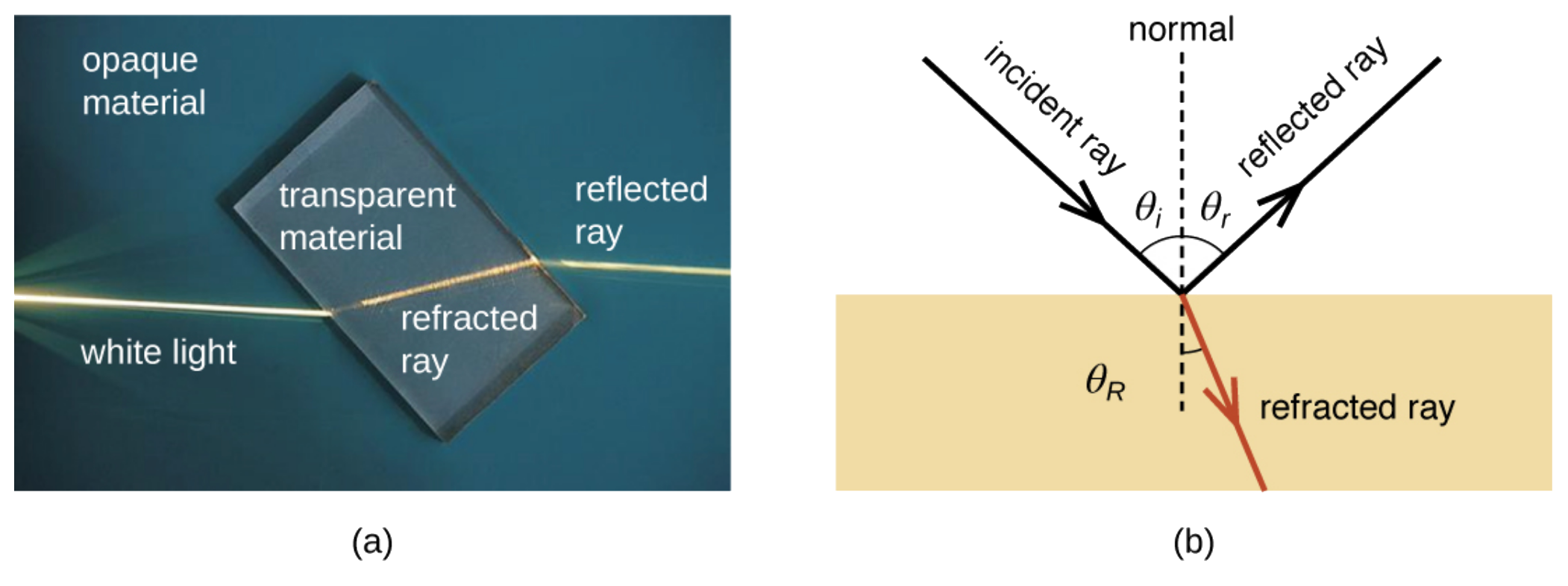
Refraction occurs when light waves change direction as they enter a new medium. As light waves move from one medium to another, their speed often changes, and this produces refraction. The angle of the incoming light affects the degree of change.
Image (a) below shows refraction occurring when light passes from one medium such as air to another such as glass, changing the direction of the light rays. Image (b) shows that light rays passing from one medium to another may be either refracted or reflected.
The refractive index of a material is a measure of the extent to which the material slows transmission speed relative to empty space. When light passes from one material to another material with a similar refractive index, little bending occurs. When the difference in the refractive indexes of materials is larger, the amount of bending is greater, as indicated in the image below, which shows the straight pole appearing to bend at an angle as it enters the water. This optical illusion is due to the large difference between the refractive indices of air and water.

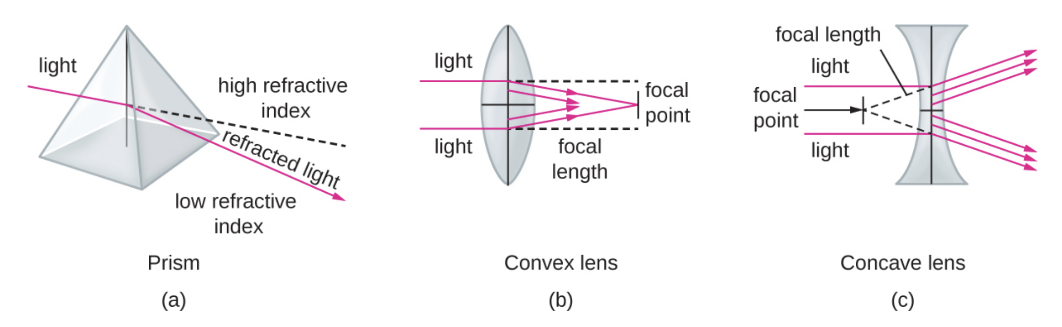
When white light hits a prism, it separates to show different colors because different frequencies of light have different refractive indices. This separation of waves is called dispersion. The image below shows a prism that separates white light into its different colors because different wavelengths of light produce different colors and are refracted at different angles.
.")
EXAMPLE
Plant stems and leaves generally appear green. When white light hits a plant, some light energy, including red and blue wavelengths, is absorbed and other frequencies of light, including green, are reflected away from the plant. When this reflected light hits receptors in the retina of the human eye, the brain perceives the color as green. Many other animals, such as pollinating insects, can see patterns on flowers that reflect EMR outside of the range of light that is visible to humans.Nonvisible EMR can be changed to visible light. Fluorescent materials, such as fluorescent dyes, absorb UV or blue light and then release the energy as photons of visible light. Because some energy is absorbed, the emitted photons are lower energy than the absorbed photons. When there is a delay between absorption and emission, the phenomenon is called phosphorescence.
The image below shows bovine pulmonary artery endothelial cells. When fluorescent dyes are absorbed by the cells, they emit brilliant colors excited by UV light under a fluorescence microscope. Various cell structures absorb different dyes. The nuclei are stained blue with 4’,6-diamidino-2-phenylindole (DAPI), microtubules are marked green by an antibody bound to fluorescein isothiocyanate (FITC), and actin filaments are marked red with phalloidin bound to tetramethylrhodamine (TRITC).

Microscopes magnify images and use the properties of light to create useful images of small objects. Magnification is the ability of a lens to enlarge the image of an object compared to the size of the real object.
EXAMPLE
A magnification of 10x means that the image appears 10 times the size of an object viewed with the naked eye.Higher magnification makes an object larger but does not necessarily mean that the image is clear. It is also important to consider resolution, which is the ability to tell that two separate points or objects are separate. A low-resolution object appears fuzzy, whereas a high-resolution image appears sharp.
The two factors that affect resolution are wavelength and numerical aperture. As the wavelength becomes shorter, it is possible to resolve smaller objects. Numerical aperture is a measure of a lens’s ability to gather light. A lens with a larger numerical aperture can gather more light than a lens with a smaller numerical aperture.
Another important consideration is contrast, which is the ability to distinguish between features in a specimen. Microbes are often relatively translucent, making it difficult to distinguish individual structures. Various types of microscopes use different features of light or electrons to increase contrast. Adjusting the amount of light on a specimen can improve contrast. Additionally, dyes that bind to some specimen structures but not others can improve contrast and make it easier to detect structures of interest.
In microscopy, lenses are used to magnify and refract light so that it meets at a single point called the image point or focus. To magnify an image, convex lenses are used. Convex lenses can focus at a closer range than the human eye, and this produces a larger image. Concave lenses and mirrors are used to redirect the light path as needed.
The focal point is the image point at which the light entering the lens is parallel. The focal length is the distance to the focal point. The positions of the focal point and focal length vary with the type of lens.
To manipulate the image, both the curvature of the lens and the distances between the object, the lens, and the “screen” (whatever detects the image) must be considered. The screen can be an eye, a computer, or something else. This is why changing lenses changes magnification and moving a specimen closer or farther from the lens brings it in and out of focus. You will learn more about the ways to adjust an image viewed through a microscope in the lesson on microscopy.
If the curvature of the lens is constant, moving an object closer to the lens moves the focal point farther from the lens. Increasing the curvature moves the image point closer to the lens and produces a larger image when the image is in focus.
EXAMPLE
Many people wear glasses or contact lenses to improve their vision. These lenses help to focus light when the lens of the eye is not sufficient. The eye may have trouble focusing on objects that are very close or very far away, for example. Some glasses have a single refractive index, whereas others (such as bifocals) may have more than one.Image (a) below shows that a lens is like a collection of prisms. When light passes through a convex lens, as shown in image (b), it is refracted toward a focal point on the other side of the lens. The focal length is the distance to the focal point. Light passing through a concave lens, as shown in image (c), is refracted away from a focal point in front of the lens.
Source: THIS TUTORIAL HAS BEEN ADAPTED FROM OPENSTAX "MICROBIOLOGY." ACCESS FOR FREE AT openstax.org/details/books/microbiology. LICENSE: CC ATTRIBUTION 4.0 INTERNATIONAL. Accessed by August 2022.
REFERENCES
Electromagnetic Radiation (Physics). (n.d.). Encyclopedia Brittanica. Retrieved July 27, 2022, from
britannica.com/science/electromagnetic-radiation
Tait, J. Flickr. Image ID 8055.CR2. Retrieved July 27, 2022, from www.flickr.com/photos/99914856@N06/16837222910.
Parker, N., Schneegurt, M., Thi Tu, A.-H., Lister, P., & Forster, B. (2016). Microbiology. OpenStax. Access for free at openstax.org/books/microbiology/pages/1-introduction.