Table of Contents |
Troubleshooting IP addressing is obviously an important skill because you're sure to run into trouble somewhere along the way. This lesson will introduce you to some diagnostic tools to identify addressing problems on an IP network.
Ping uses an Internet Control Message Protocol (ICMP) echo request and replies to a test if a host IP stack is initialized and alive on the network.
Let’s use the diagram below as an example of basic IP trouble. Sally can’t log in to the Windows server.
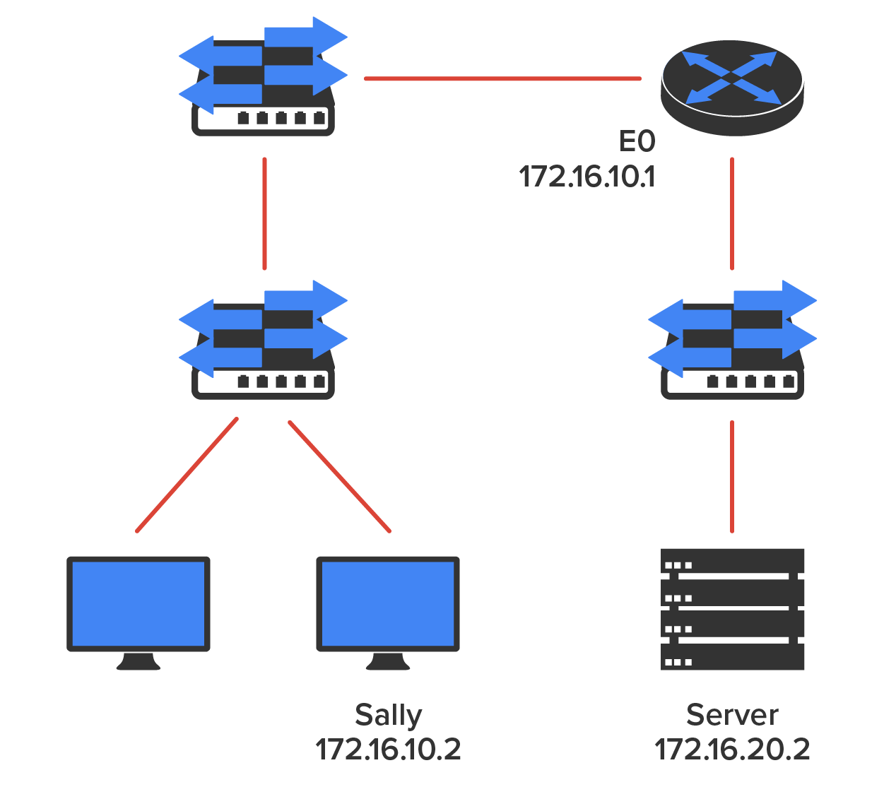
Let’s get started by going over the basic troubleshooting steps. They’re pretty simple but important, nonetheless. Pretend you’re at Sally’s host and she’s complaining that she can’t communicate to a server that just happens to be on a remote network: Open a command prompt window on Sally’s host and ping 127.0.0.1.
C:\>ping 127.0.0.1
Pinging 127.0.0.1 with 32 bytes of data:
Reply from 127.0.0.1: bytes=32 time<1ms TTL=128
Reply from 127.0.0.1: bytes=32 time<1ms TTL=128
Reply from 127.0.0.1: bytes=32 time<1ms TTL=128
Reply from 127.0.0.1: bytes=32 time<1ms TTL=128
Ping statistics for 127.0.0.1:
Packets: Sent = 4, Received = 4, Lost = 0 (0% loss),
Approximate round trip times in milli-seconds:
Minimum = 0ms, Maximum = 0ms, Average = 0ms
This is the diagnostic, or loopback, address, and if you get a successful ping, your IP stack is considered to be initialized. If it fails, then you have an IP stack failure and need to reinstall TCP/IP on the host.
If that’s successful, your network interface card (NIC) is functioning. If it fails, there is a problem with the NIC. Success here doesn’t mean that a cable is plugged into the NIC, only that the IP protocol stack on the host can communicate to the NIC (via the LAN driver).C:\>ping 172.16.10.2
Pinging 172.16.10.2 with 32 bytes of data:
Reply from 172.16.10.2: bytes=32 time<1ms TTL=128
Reply from 172.16.10.2: bytes=32 time<1ms TTL=128
Reply from 172.16.10.2: bytes=32 time<1ms TTL=128
Reply from 172.16.10.2: bytes=32 time<1ms TTL=128
Ping statistics for 172.16.10.2:
Packets: Sent = 4, Received = 4, Lost = 0 (0% loss),
Approximate round trip times in milli-seconds:
Minimum = 0ms, Maximum = 0ms, Average = 0ms
If the ping works, it means that the NIC is plugged into the network and can communicate on the local network. If it fails, you have a local physical network problem that could be anywhere from the NIC to the router.C:\>ping 172.16.10.1
Pinging 172.16.10.1 with 32 bytes of data:
Reply from 172.16.10.1: bytes=32 time<1ms TTL=128
Reply from 172.16.10.1: bytes=32 time<1ms TTL=128
Reply from 172.16.10.1: bytes=32 time<1ms TTL=128
Reply from 172.16.10.1: bytes=32 time<1ms TTL=128
Ping statistics for 172.16.10.1:
Packets: Sent = 4, Received = 4, Lost = 0 (0% loss),
Approximate round trip times in milli-seconds:
Minimum = 0ms, Maximum = 0ms, Average = 0ms
C:\>ping 172.16.20.2
Pinging 172.16.20.2 with 32 bytes of data:
Reply from 172.16.20.2: bytes=32 time<1ms TTL=128
Reply from 172.16.20.2: bytes=32 time<1ms TTL=128
Reply from 172.16.20.2: bytes=32 time<1ms TTL=128
Reply from 172.16.20.2: bytes=32 time<1ms TTL=128
Ping statistics for 172.16.20.2:
Packets: Sent = 4, Received = 4, Lost = 0 (0% loss),
Approximate round trip times in milli-seconds:
Minimum = 0ms, Maximum = 0ms, Average = 0ms
If that works, then you know that you have IP communication between the local host and the remote server. You also know that the remote physical network is working.C:\>ping 172.16.20.2
Pinging 172.16.20.2 with 32 bytes of data:
Reply from 172.16.20.2: bytes=32 time<1ms TTL=128
Reply from 172.16.20.2: bytes=32 time<1ms TTL=128
Reply from 172.16.20.2: bytes=32 time<1ms TTL=128
Reply from 172.16.20.2: bytes=32 time<1ms TTL=128
Ping statistics for 172.16.20.2:
Packets: Sent = 4, Received = 4, Lost = 0 (0% loss),
Approximate round trip times in milli-seconds:
Minimum = 0ms, Maximum = 0ms, Average = 0ms
If the user still can’t communicate with the server even though steps 1 through 4 were successful, you probably have some type of name resolution problem and need to check your Domain Name System (DNS) settings. But if the ping to the remote server fails, then you know you have some type of remote physical network problem and need to go to the server and follow steps 1 through 3 until you find the snag.
Before we move on to determining IP address problems and how to fix them, review some DOS commands that you can use to help troubleshoot your network from a PC.
Traceroute describes the hops that a packet makes from router to router on the way to its destination. It displays the list of routers on a path to a network destination by using Time-to-Live (TTL) time-outs and ICMP error messages. This command will work on a router, MAC, or Linux box but not from a Windows command prompt.
This command is the same as traceroute, but it is a Microsoft Windows command and will not work on other devices, like a Cisco router or a Unix computer. The arp-a command displays IP-to-MAC-address mappings on a Windows PC. ipconfig /all is used only from a DOS prompt.
Once you’ve gone through all these steps and used the appropriate DOS commands if necessary, what do you do if you find a problem? How do you go about fixing an IP address configuration error? That’s exactly what you’re going to learn about next—how to determine specific IP address problems and what you can do to fix them.
It is common for a host, router, or other network device to be configured with the wrong IP address, subnet mask, or default gateway. Because this happens way too often, you should know how to both determine and fix IP address configuration errors.
Once you’ve worked through the four basic steps of troubleshooting and determined there is a problem, you obviously then need to find and fix it.
It really helps to draw out the network and IP addressing scheme. If it’s already done, consider yourself lucky and go buy a lottery ticket because although it should be done, it rarely is. And if it is, it’s usually outdated or inaccurate anyway. Typically, it is not done, and you’ll probably just have to bite the bullet and start from scratch.
Once you have your network accurately drawn out, including the IP addressing scheme, you need to verify each host’s IP address, mask, and default gateway address to determine the problem.
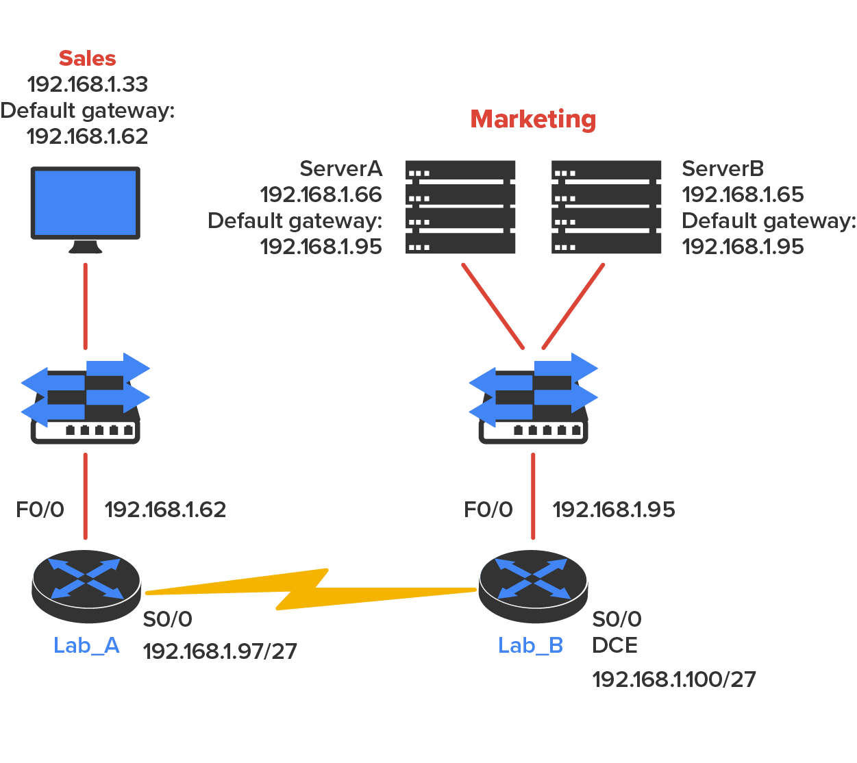
Let’s check out the example illustrated in the diagram below. A user in the sales department calls and tells you that she can’t get to server A in the marketing department. You ask her if she can get to server B in the marketing department, but she doesn’t know because she doesn’t have rights to log on to that server. What do you do?
IN CONTEXT
You ask the client to go through the four troubleshooting steps that you learned about in the preceding section. Steps 1 through 3 work, but step 4 fails. By looking at the figure, can you determine the problem? Look for clues in the network drawing. First, the WAN link between the Lab_A router and the Lab_B router shows the mask as a /27. You should already know that this mask is 255.255.255.224 and then determine that all networks are using this mask. The network address is 192.168.1.0. What are our valid subnets and hosts? 256 – 224 = 32, so this makes our subnets 0, 32, 64, 96, 128, and so on. So, by looking at the figure, you can see that subnet 32 is being used by the sales department, the WAN link is using subnet 96, and the marketing department is using subnet 64.
Now you have to determine what the valid host ranges are for each subnet. From what you learned at the beginning of this chapter, you should now be able to easily determine the subnet address, broadcast addresses, and valid host ranges. The valid hosts for the sales LAN are 33 through 62—the broadcast address is 63 because the next subnet is 64, right? For the marketing LAN, the valid hosts are 65 through 94 (broadcast 95), and for the WAN link, 97 through 126 (broadcast 127). By looking at the figure, you can determine that the default gateway on the Lab_B router is incorrect. That address is the broadcast address of the 64 subnet, so there’s no way it could be a valid host.
The diagram below shows another network problem. A user in the sales LAN can’t get to server B. You have the user run through the four basic troubleshooting steps and find that the host can communicate with the local network but not with the remote network. Find and define the IP addressing problem.

If you use the same steps used to solve the last problem, you can see first that the WAN link again provides the subnet mask to use— /29, or 255.255.255.248. You need to determine what the valid subnets, broadcast addresses, and valid host ranges are to solve this problem.
The 248 mask is a block size of 8 (256 – 248 = 8), so the subnets both start and increment in multiples of 8. By looking at the figure, you see that the sales LAN is in the 24 subnet, the WAN is in the 40 subnet, and the marketing LAN is in the 80 subnet. Can you see the problem yet? The valid host range for the sales LAN is 25–30, and the configuration appears correct. The valid host range for the WAN link is 41–46, and this also appears correct. The valid host range for the 80 subnet is 81–86, with a broadcast address of 87 because the next subnet is 88. Server B has been configured with the broadcast address of the subnet.
Now that you can figure out misconfigured IP addresses on hosts, what do you do if a host doesn’t have an IP address and you need to assign one? What you need to do is look at other hosts on the LAN and figure out the network, mask, and default gateway. Let’s take a look at a couple of examples of how to find and apply valid IP addresses to hosts.
You need to assign a server and router IP addresses on a LAN. The subnet assigned on that segment is 192.168.20.24/29, and the router needs to be assigned the first usable address and the server the last valid host ID. What are the IP address, mask, and default gateway assigned to the server?
EXAMPLE
To answer this, you must know that a /29 is a 255.255.255.248 mask, which provides a block size of 8. The subnet is known as 24, the next subnet in a block of 8 is 32, so the broadcast address of the 24 subnet is 31, which makes the valid host range 25–30:As another example, let’s take a look at the diagram below and solve this problem.
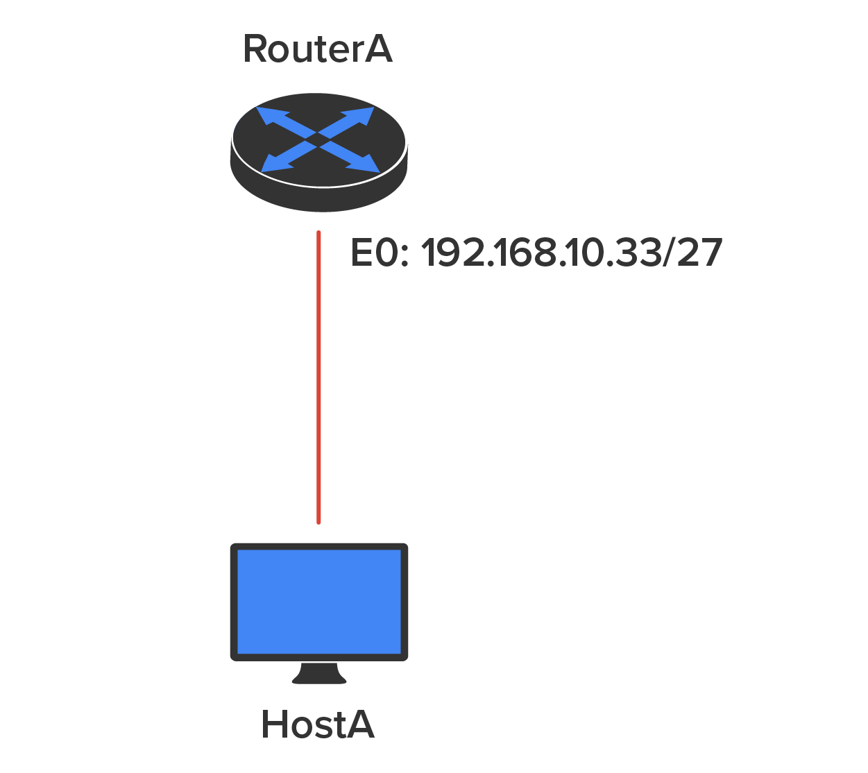
Look at the router’s IP address on Ethernet0. What IP address, subnet mask, and valid host range could be assigned to the host?
EXAMPLE
The IP address of the router’s Ethernet0 is 192.168.10.33/27. As you already know, a /27 is a 224 mask with a block size of 32. The router’s interface is in the 32 subnet. The next subnet is 64, so that makes the broadcast address of the 32 subnet 63 and the valid host range 33–62:The following figure shows two routers with Ethernet configurations already assigned. What are the host addresses and subnet masks of hosts A and B?
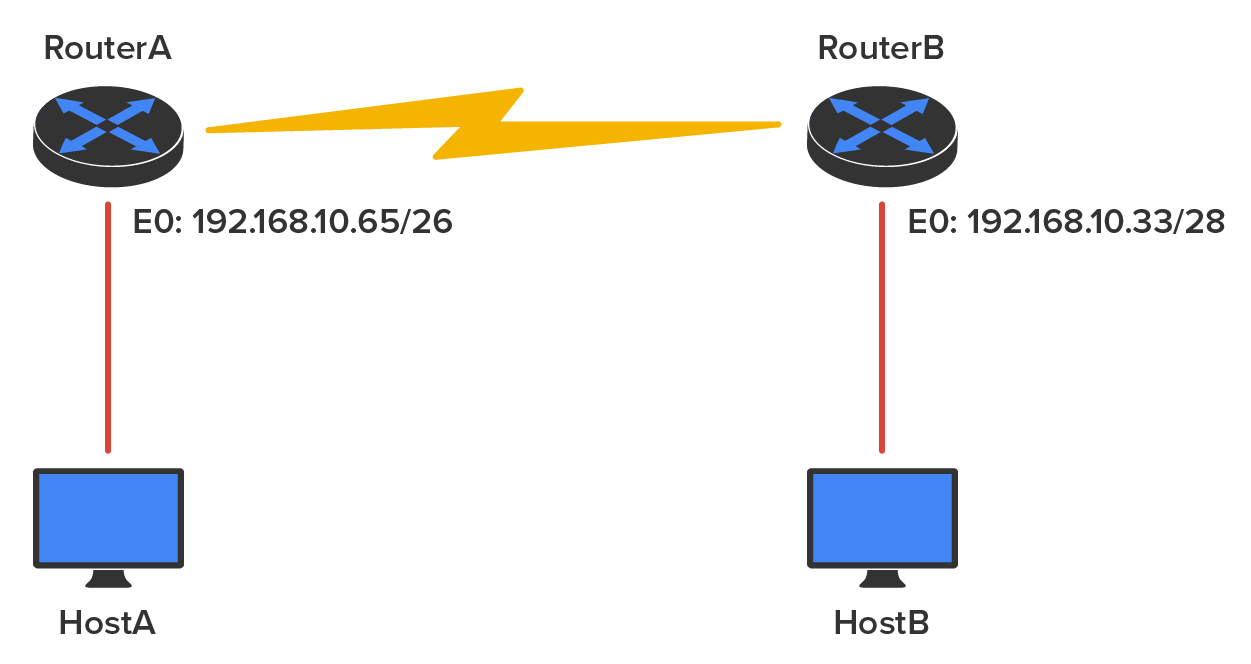
Router A has an IP address of 192.168.10.65/26 and router B has an IP address of 192.168.10.33/28. What are the host configurations? Router A Ethernet0 is in the 192.168.10.64 subnet, and router B Ethernet0 is in the 192.168.10.32 network:
HostA IP address: 192.168.10.66–126
HostA mask: 255.255.255.192
HostA default gateway: 192.168.10.65
HostB IP address: 192.168.10.34–46
HostB mask: 255.255.255.240
HostB default gateway: 192.168.10.33
The diagram below shows two routers; you need to configure the S0/0 interface on Router A. The network assigned to the serial link is 172.16.16.0/22. What IP address can be assigned?
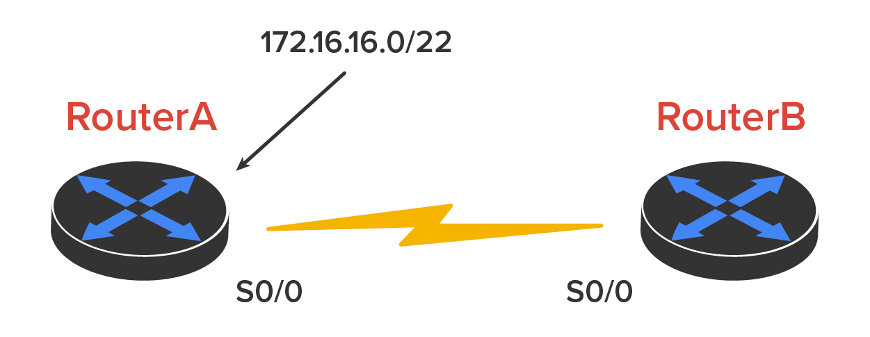
First, you must know that a /22 CIDR is 255.255.252.0, which makes a block size of 4 in the third octet. Because 16 is listed, the available range is 16.1 through 19.254; so, for example, the IP address S0/0 could be 172.16.18.255 because it is within the range.
You have one Class C network ID, and you need to provide one usable subnet per city while allowing enough usable host addresses for each city specified in the diagram below What is your subnet mask?
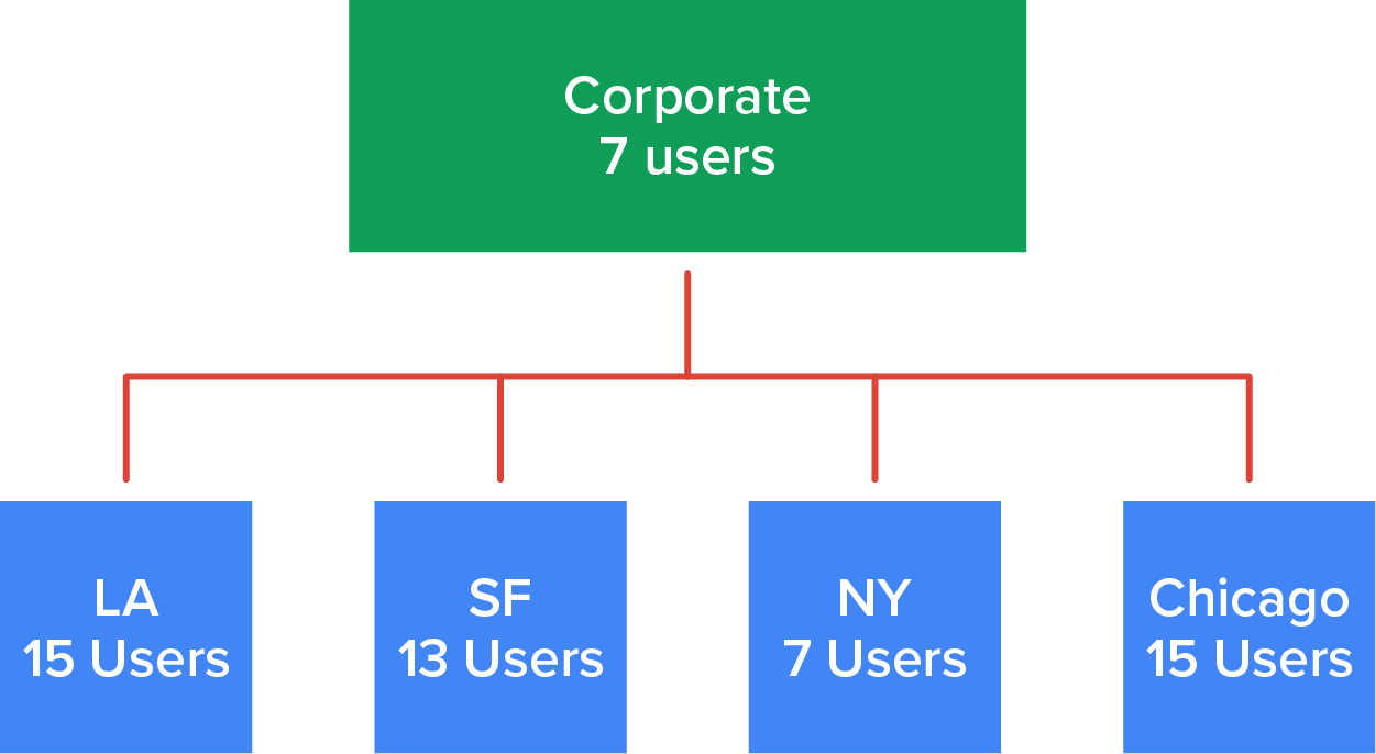
Five subnets are needed, and the Chicago office needs 15 users (always look for the network that needs the most hosts). What block size is needed for the Chicago office? 32. (Remember, you cannot use a block size of 16 because you always have to subtract 2!) What mask provides you with a block size of 32? 224. This provides 8 subnets, each with 30 hosts.
Source: This content and supplemental material has been adapted from CompTIA Network+ Study Guide: Exam N10-007, 4th Edition. Source Lammle: CompTIA Network+ Study Guide: Exam N10-007, 4th Edition - Instructor Companion Site (wiley.com)