Table of Contents |
In the DoD model, there are two main reasons for the internet layer’s existence: routing and providing a single network interface to the upper layers. Remember that the internet layer maps to Layer 3 (network) of the OSI model.
None of the other upper- or lower-layer protocols has any functions related to routing. The task of forwarding packets from one network to another is performed entirely by the internet layer. The internet layer’s second duty is to provide a single network interface to the upper-layer protocols.
Internet Protocol (IP) is essentially the internet layer (Layer 3). The other protocols found here merely exist to support it. IP has the big picture and can be said to “see all” in that it is aware of all the interconnected networks. It can do this because all the machines in the network have a software, or logical, address called an IP address, which we will cover more thoroughly in the next tutorial.
IP looks at each packet’s destination address. Then, using a routing table, it decides where a packet is to be sent next, choosing the best path. The protocols of the network access layer at the bottom of the DoD model, which maps to Layer 2 of the OSI model, do not possess IP’s view of the entire network; they deal only with physical links on local area networks.
Identifying devices on networks requires answering these two questions:
IP receives segments from the host-to-host layer and fragments them into packets, if necessary. IP then reassembles the packets back into segments on the receiving side. Each packet is assigned the IP address of the sender and of the recipient. Each router (Layer 3 device) that receives a packet makes routing decisions based on the packet’s destination IP address.
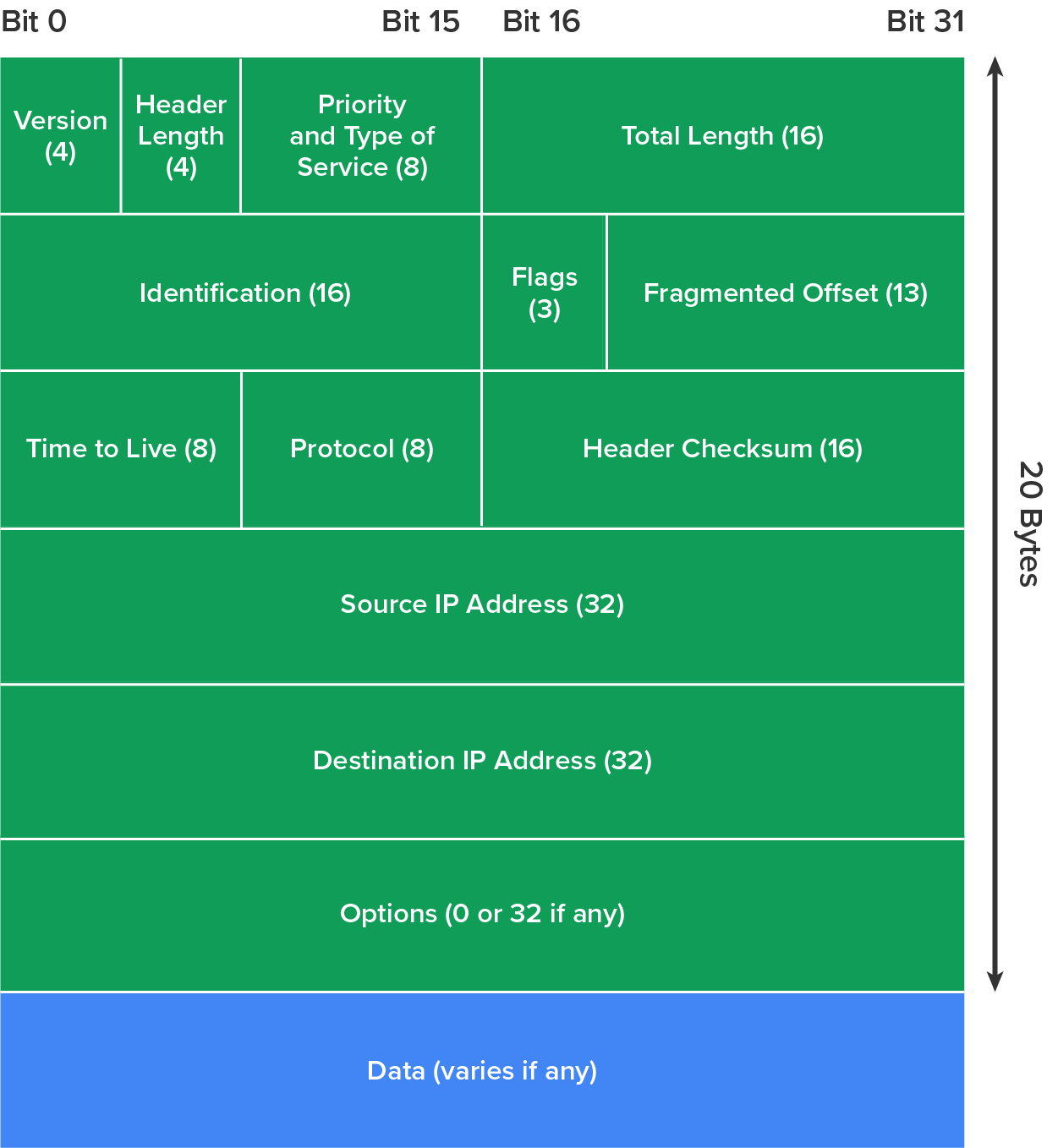
The diagram below shows an IPv4 header. This will give you an idea of what IP has to go through every time user data are sent from the upper layers to a remote network.
Internet Control Message Protocol (ICMP) works at the internet layer, which maps to Layer 3 of the OSI model. It is used by IP for many different services. ICMP is a management protocol and messaging service provider for IP. Its messages are carried as IP packets.
The following are some common events and messages related to ICMP and the two most popular programs that use ICMP.
Destination Unreachable
If a router cannot send an IP packet any further, it uses ICMP to send a message back to the sender, advising it of the situation. For example, take a look at the diagram below, which shows that the Ethernet interface of the Lab B router is down.
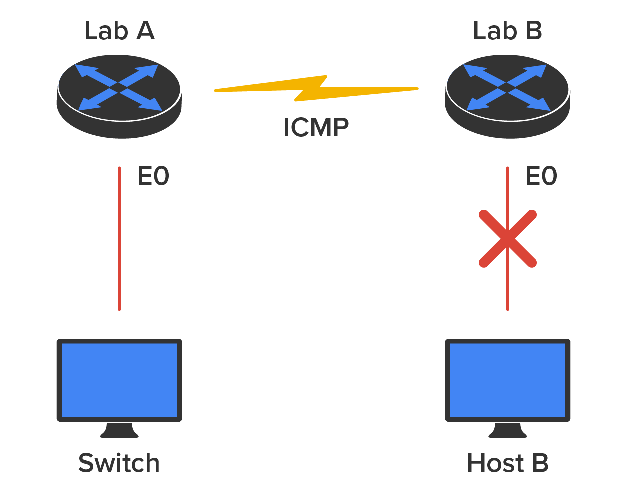
When Host A sends a packet destined for Host B, the Lab B router will send an “ICMP Destination Unreachable” message back to the sending device (directly to Host A, in this example).
Buffer Full
If a router’s memory buffer for receiving incoming packets is full, it will use ICMP to send out this message until the congestion clears.
Hops
Each IP packet is allotted a certain number of routers, called tracert, to pass through. If a packet reaches its limit of hops before arriving at its destination, the last router to receive it deletes it. The router then uses ICMP to send a message, informing the sending machine of the loss of its packet.
Ping
Ping uses ICMP echo request and reply messages to check the physical and logical connectivity of machines in an internetwork.
Traceroute
Traceroute uses IP packet time-to-live time-outs to discover the path a packet takes as it traverses an internetwork.
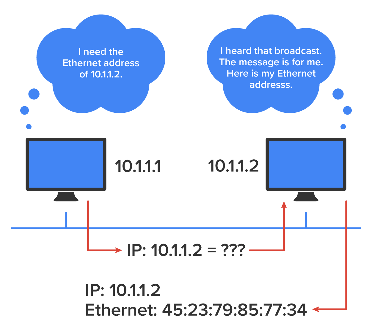
Address Resolution Protocol (ARP) finds the OSI Layer 2 hardware MAC address of a host from a known IP address. Here’s how it works: When IP has a packet to send, it must inform a MAC protocol, such as Ethernet, of the destination’s hardware address on the local network. If IP doesn’t find the destination host’s hardware address in the ARP cache, it uses ARP to find this information.
ARP interrogates the local network by sending out a broadcast asking the machine with the specified IP address to reply with its hardware MAC address. So, basically, ARP translates the Layer 3 IP address into a Layer 2 MAC address. The illustration below shows how an ARP broadcast looks to a local network.
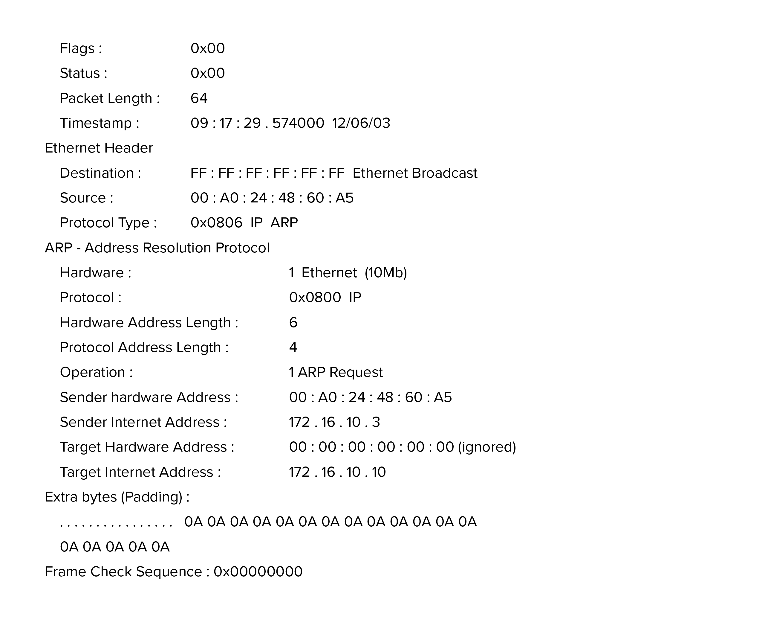
The trace below shows an ARP broadcast; notice that the destination hardware address is unknown and is all 0s in the ARP header. In the Ethernet header, a destination of all Fs in hex (all 1s in binary), a hardware address broadcast, is used to make sure all devices in the local link receive the ARP request.
When an IP machine happens to be a diskless machine, it has no way of initially knowing its IP address. But it does know its MAC address. Reverse Address Resolution Protocol (RARP) discovers the identity of the IP address for diskless machines by sending out a packet that includes its MAC address and a request for the IP address assigned to that MAC address. A designated machine, called an RARP server, responds with the answer. RARP uses the information it does know about the machine’s MAC address to learn its IP address and complete the machine’s ID portrait.
EXAMPLE
The illustration below shows a diskless workstation asking for its IP address with an RARP broadcast.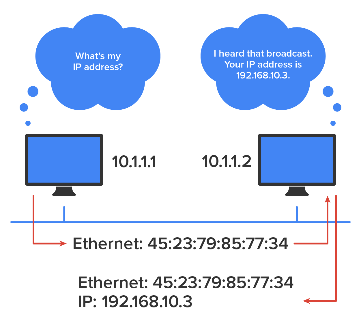
The process of data encapsulation was briefly introduced earlier in the course. When a host transmits data across a network to another device, the data undergo encapsulation: The data are wrapped with protocol information at each layer of the OSI model. Each layer communicates only with its peer layer in the receiving device.
To communicate and exchange information, each layer uses Protocol Data Units (PDUs). These hold the control information attached to the data at each layer of the model. They are usually attached to the header in front of the data field, but they can also be in the trailer or end.
Each PDU attaches to the data by encapsulating them at each layer of the OSI model, and each has a specific name depending on the information provided in each header. This PDU information is read only by the peer layer in the receiving device. After it is read, it is stripped off, and the data are then handed to the next layer up.
EXAMPLE
The diagram below shows the PDUs and how they attach control information to each layer. This figure demonstrates how the upper-layer user data are converted for transmission on the network. The data stream is then handed down to the transport layer, which sets up a virtual circuit to the receiving device by sending over a synch packet. Next, the data stream is broken up into smaller pieces, and a transport layer header (a PDU) is created and attached to the header of the data field; now, the piece of data is called a “segment.” Each segment is sequenced, so the data stream can be put back together on the receiving side exactly as it was transmitted.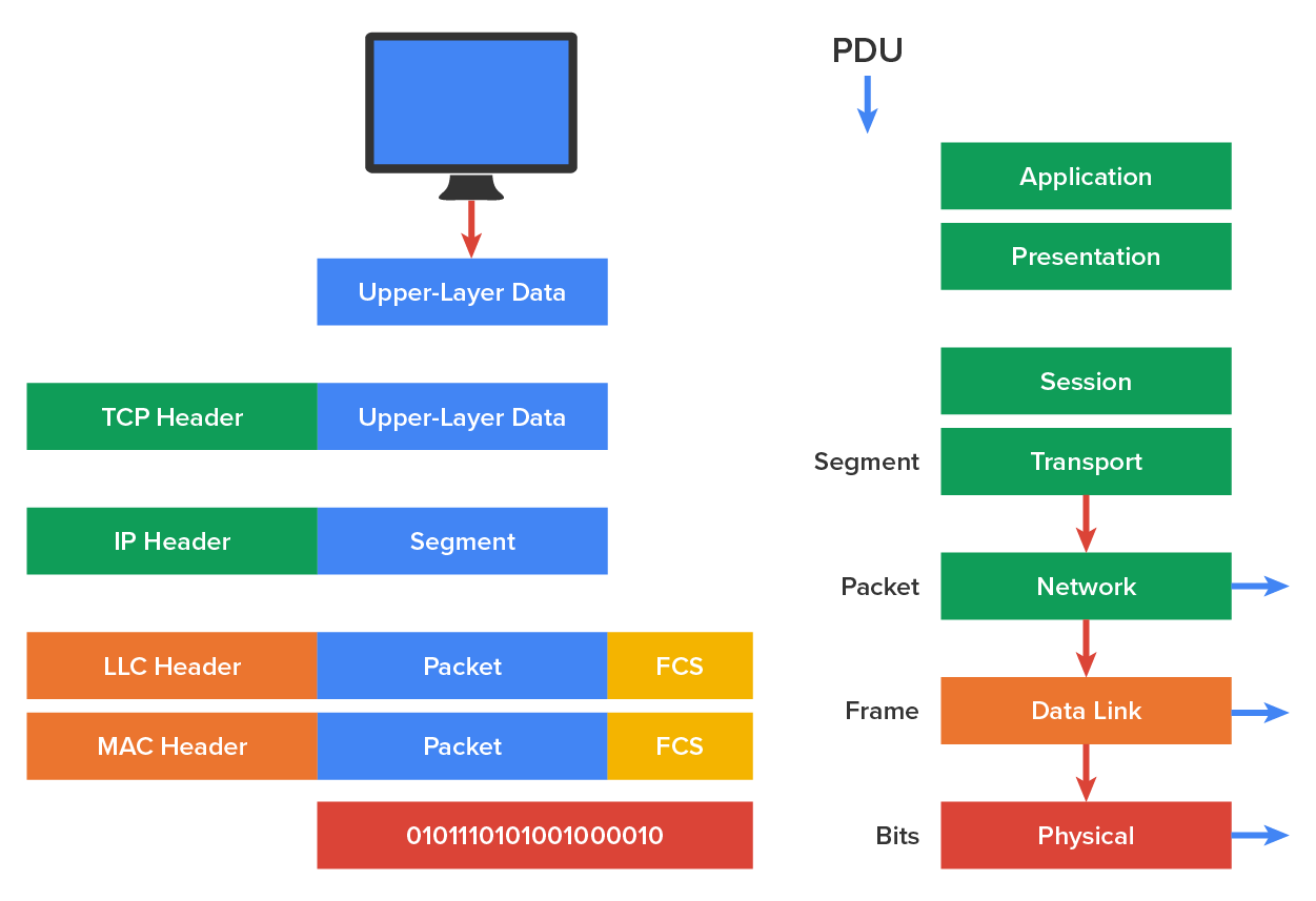
Each segment is then handed to the OSI Layer 3 (network) for network addressing and routing through the internetwork. Logical addressing, typically the IP address, is used to get each segment to the correct network. The Layer 3 protocol adds a control header to the segment handed down from Layer 4 (transport), and what we have now is called a packet, which can also be called an IP datagram. Remember that Layer 4 and Layer 3 work together to rebuild a data stream on a receiving host, but it is Layer 2 that places their PDUs on a local network segment, which is the only way to get the information to a router or host.
Source: This content and supplemental material has been adapted from CompTIA Network+ Study Guide: Exam N10-007, 4th Edition. Source Lammle: CompTIA Network+ Study Guide: Exam N10-007, 4th Edition - Instructor Companion Site (wiley.com)