Table of Contents |
The developments that led to the first microscopes began in the 1500s. During these years, eyeglass makers in the Netherlands began to develop the techniques that would later be used in microscopes. Italian astronomer Galileo Galilei (1564–1642) developed a compound microscope to examine insect parts. In compound microscopes, light passes through two lenses. In contrast, light passes through only one lens in a simple microscope.
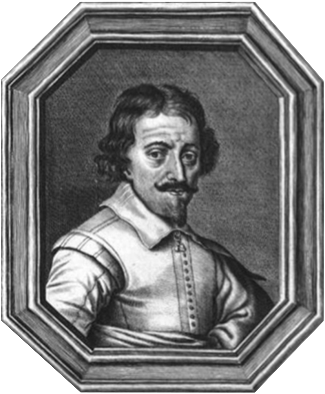
There is uncertainty about exactly who developed the very first microscope. Dutch spectacle-makers Hans and Zaccharias Janssen worked secretively to develop microscopes and telescopes. Zaccharias Janssen (pictured left), along with his father Hans, may have invented the telescope, the simple microscope, and the compound microscope during the late 1500s or early 1600s. The historical evidence is inconclusive. Because they did not publish their work, it is unclear exactly what they were able to view. Even their dates of birth and death are unknown.
Around about the same time as the Janssens, their neighbor Hans Lippershey also worked on developing microscopes and telescopes. Lippershey often receives credit for inventing the first telescope. However, he also did not publish, and therefore, the details of his work are fuzzy.
More is known about individuals who published and disseminated their work widely. Robert Hooke (1635–1703) developed a compound microscope in 1665, as shown in image (a) below. This microscope used three lenses and a stage light to view cork cells, and he named them “cells”. Cork cells are dead plant cells with stiff cell walls surrounding empty regions that appeared to be filled with air. Hooke described cork cells as “small Boxes or Bladders of Air” and noted that they resembled a “Honey-comb”. He also observed that each “Cavern, Bubble, or Cell” was distinct. Hooke published his work on microscopy through the Royal Society. His bestselling book, published in 1865, was called Micrographia.
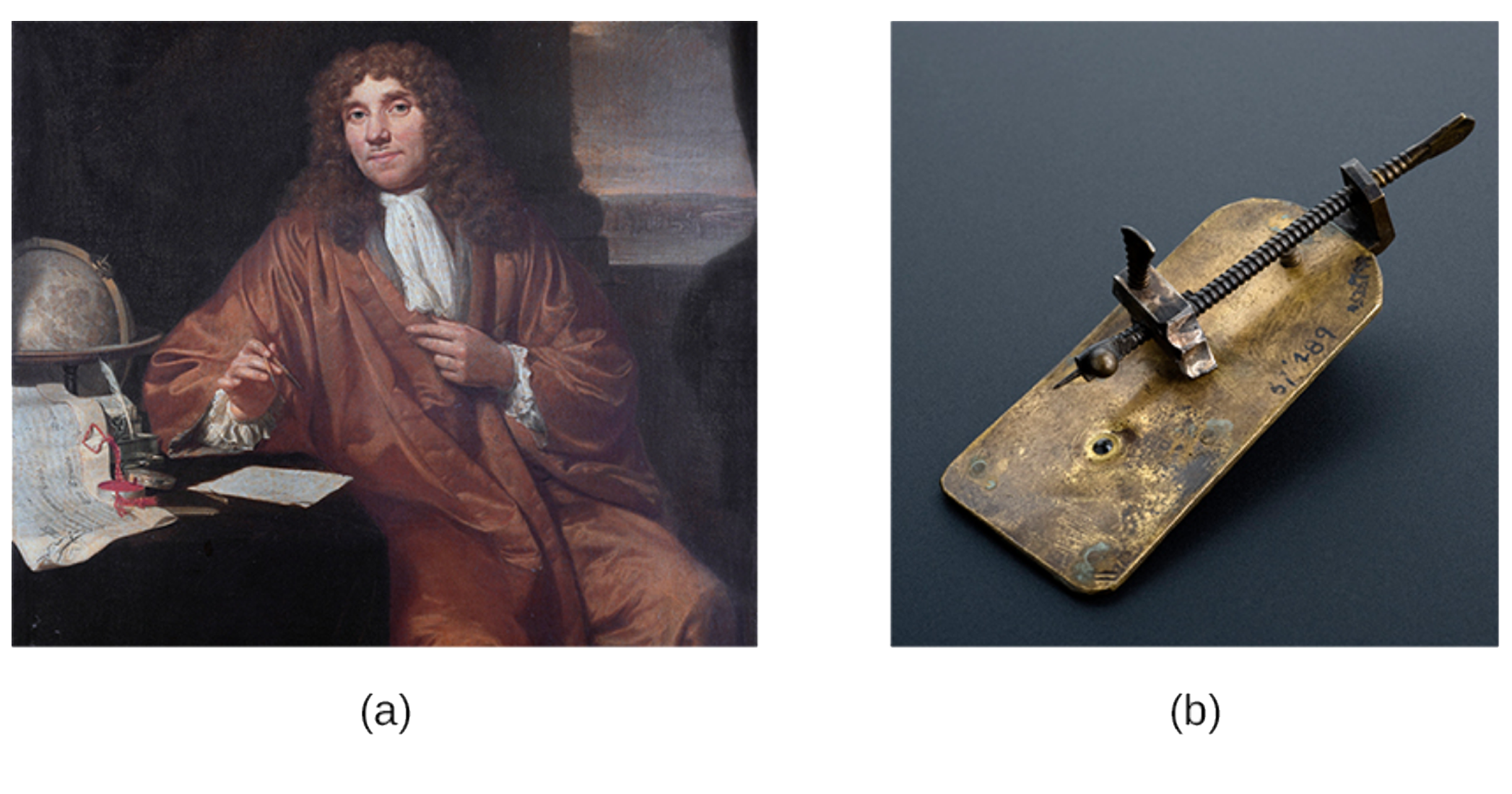
The earliest known clearly identifiable drawings of microscopic organisms were made by Antonie van Leeuwenhoek (1632–1723). Van Leeuwenhoek was a Dutch fabric seller. He became interested in making lenses, possibly to view the thread. Van Leeuwenhoek developed a single-lens compound microscope that magnified specimens by 300x their original size. This discovery allowed Antonie Van Leeuwenhoek to be able to see many types of microorganisms, including bacteria, protozoa, and human cells (such as spermatozoa). When he sent a series of letters describing his observations to the Royal Society of London in 1674, people initially were skeptical. He became well-known as people realized that his observations of previously unknown organisms were real. As a result, he is sometimes called the “Father of Microbiology”.
Van Leeuwenhoek is often given credit for developing a microscope through which he could successfully view microbes, although it is not certain whether he was definitely the first. He called these organisms “animalcules” and “wee little beasties.” Even though van Leeuwenhoek’s microscopes were simple microscopes (as seen in this replica in image b, above), they were more powerful and provided better resolution than the compound microscopes of his day.
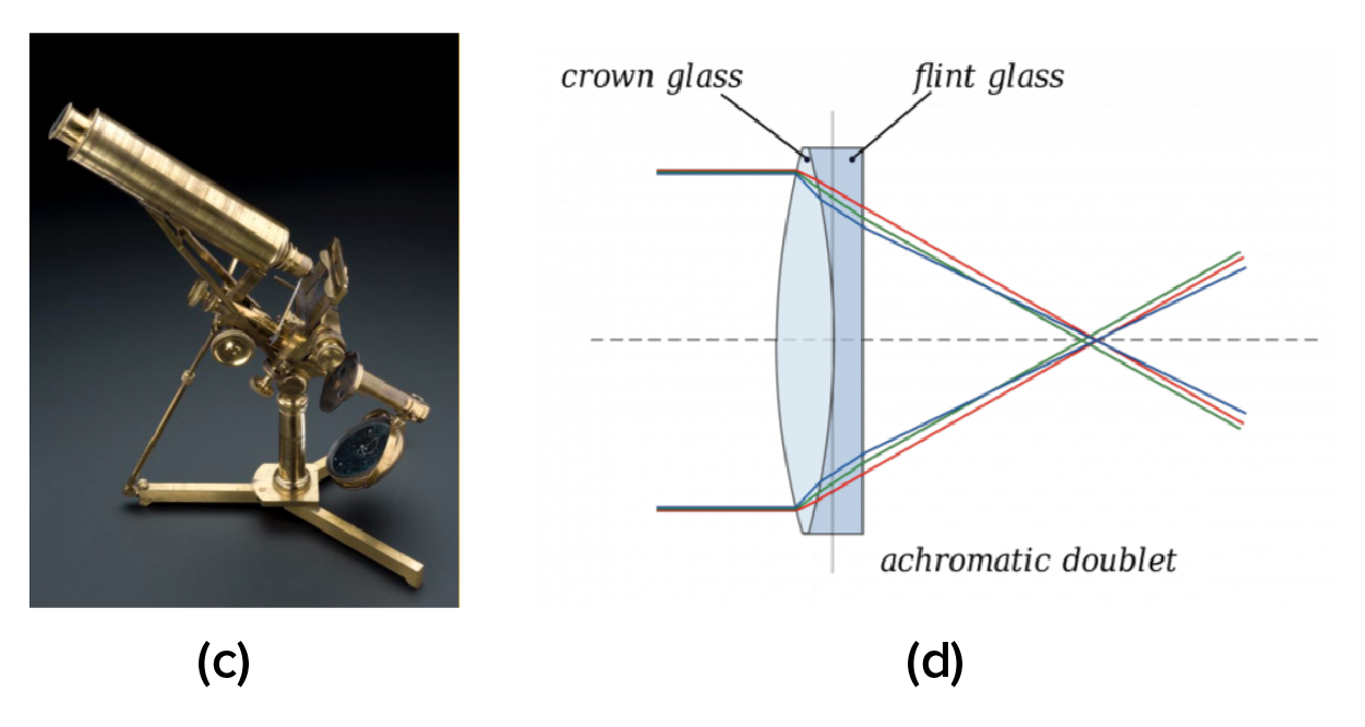
Joseph Jackson Lister (1786–1869) was a British physicist and surgeon who modernized the light microscope (image c, below). In 1830, Lister developed an achromatic compound lens (image d, below) that limited the color reflections and eliminated spherical aberration, which is where objects appear circular when viewed. Lister did this by layering two lenses, one that is concave with one that is convex. Layering these lenses lowered the dispersion of light wavelengths and created the modern compound microscope.
The following video describes the history of microscopy:
| Name | Discovery |
|---|---|
| Italian astronomer Galileo Galilei (1564–1642) | Developed a compound microscope. |
| Dutch spectacle makers Hans and Zaccharias Janssen | May have invented the telescope, the simple microscope, and the compound microscope in the late 1500s or early 1600s. |
| Hans Lippershey | Developed microscopes and telescopes around the same time as the Janssens and is credited with developing the telescope. |
| Dutch fabric maker Antonie van Leeuwenhoek (1632–1723) | Observed and reported on small organisms viewed using a simple microscope. |
| Englishman Robert Hooke (1635–1703) | Viewed and named cork cells; published Micrographia. |
| British surgeon Joseph Jackson Lister (1827–1912) | Developed the first essentially modern light microscope in 1830 (also developed techniques to reduce surgical infections). |
The first microscopes were light microscopes. Brightfield microscopes are probably the most commonly used and widely-available light microscopes at present. You will learn more about other types of light microscopes later in the lesson.
Compound light microscopes pass light through a specimen and through at least two lenses to reach the viewer’s eyes. Light that does not pass through the specimen is bright because it passes only through clear lenses on its way to the viewer. As a result, the specimen is dark and the background is bright. The appearance of the image results from the ways that structures in the specimen differentially transmit, absorb, reflect, and refract light.
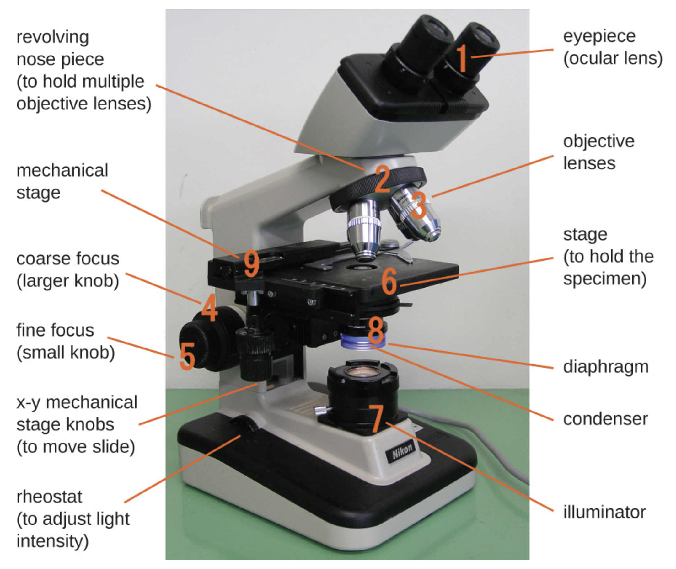
To see the specimen, the viewer looks through one or two eyepieces that each contain an ocular lens to magnify the specimen. Brightfield microscopes with one eyepiece are called monocular and those with two eyepieces are called binocular.
The image is magnified by the ocular lens and by an objective lens that varies in magnification. The viewer turns a revolving nosepiece to change the magnification by moving the cylindrical objective containing the desired objective lens over the specimen. Objective lenses are generally labeled on the outside with their magnification and longer objectives magnify more than shorter objectives.
When a brightfield microscope is used, the specimen to be viewed is placed on a slide. To view a slide using a brightfield microscope, the slide must be placed on a platform called the stage. Some stages have a mechanical stage that has knobs that allow the specimen to be moved very precisely by turning the dials.
Once the slide is in place, the coarse focusing knob and fine focusing knob are used to bring the image into focus. The coarse focusing knob is used to move the stage of a microscope over relatively large distances at low magnifications. This is used for large-scale movements with 4x and 10x objectives. The fine focusing knob is used to move the stage of a microscope over relatively small distances. This is used for small-scale movements to precisely focus on a specimen. It is the only focusing knob that can be used at magnifications above 10x.
The image can be improved by adjusting the light reaching the specimen. The image is formed by light that travels upward through the specimen from an illuminator. The illuminator is often a high-intensity light bulb below the stage. There is a small opening in the stage that allows light to reach the specimen. Below this opening, there is a condenser lens that focuses light from the illuminator on the specimen resting on the stage above. A knob can be used to move the condenser as needed.
Between the condenser lens and the stage, there is a diaphragm that can be opened or closed to adjust the amount of light reaching the specimen. It is often helpful to adjust the amount of light reaching the specimen when the magnification is changed because images become dimmer as the magnification is increased. This is because the amount of light per unit area of the image decreases with increasing magnification. Additionally, adjusting the light can improve contrast. Brightness can also be adjusted using a rheostat that controls the intensity of the illuminator.
As light passes through the specimen, it interacts with chromophores. These are pigments that absorb and reflect particular pigments of light. Stains are chemicals used to artificially add chromatophores to a specimen.
Because glass and air have different refractive indices, some light can be lost as it moves through the glass of a slide, then through air, then through the glass of the objective lens. Resolution can be improved by using an oil immersion lens like the one below in the below image (a) and immersion oil. Immersion oil with a similar refractive index to glass can be placed between the slide and the objective to reduce the amount of light lost due to refraction. A variety of oils can be used for different types of light.
EXAMPLE
Oil immersion lenses like the one in the below image (a) are used to improve resolution. Image (b) shows that because immersion oil and glass have very similar refractive indices, there is a minimal amount of refraction before the light reaches the lens. Without immersion oil, light scatters as it passes through the air above the slide, degrading the resolution of the image.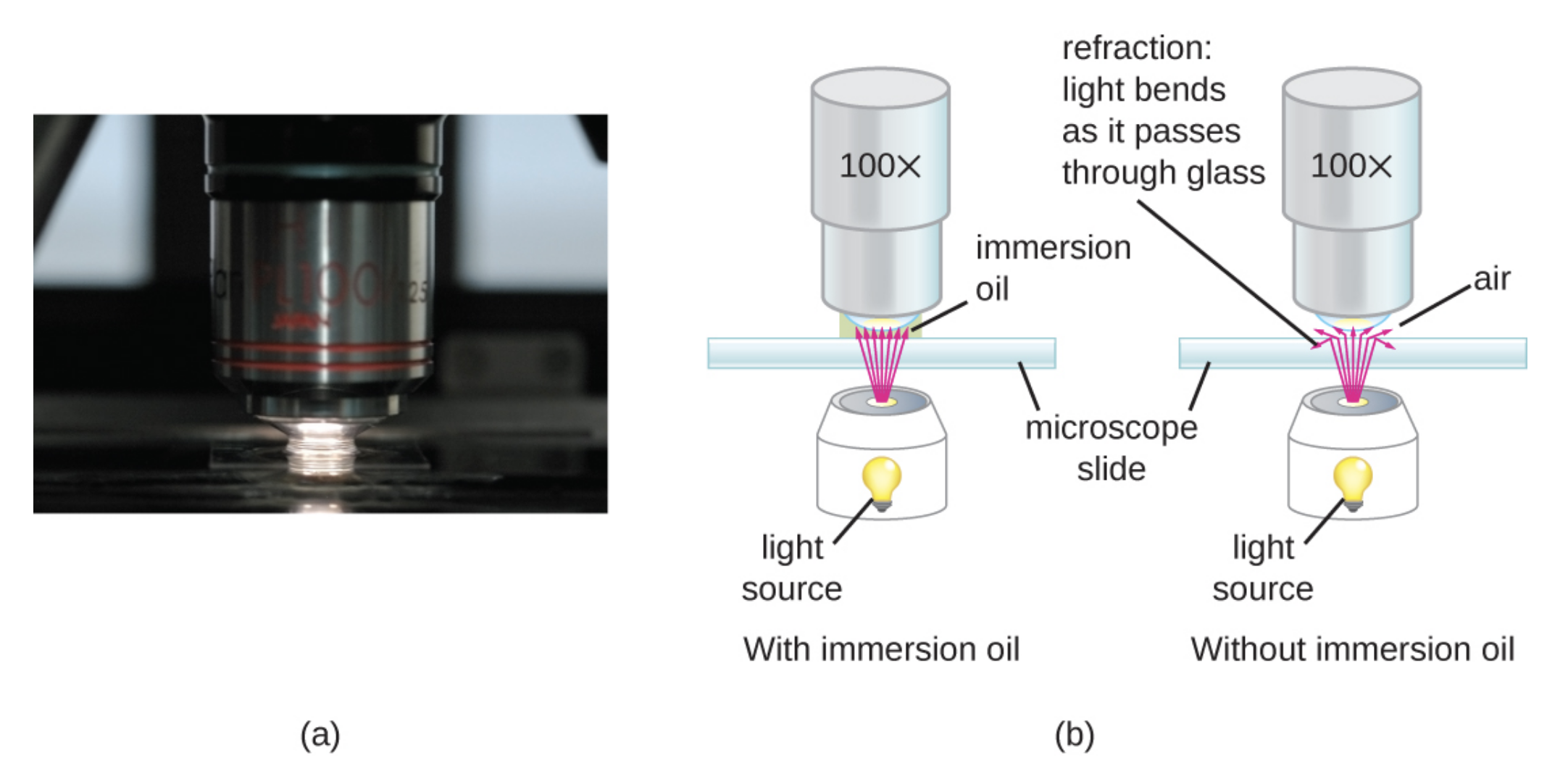
The following video describes and identifies the parts of a compound microscope:
It is important to keep in mind that microscopes are costly. They can range from a few hundred dollars apiece to thousands of dollars. For this reason, it is essential that you care for any microscopes you come in contact with. The following are key principles to follow.
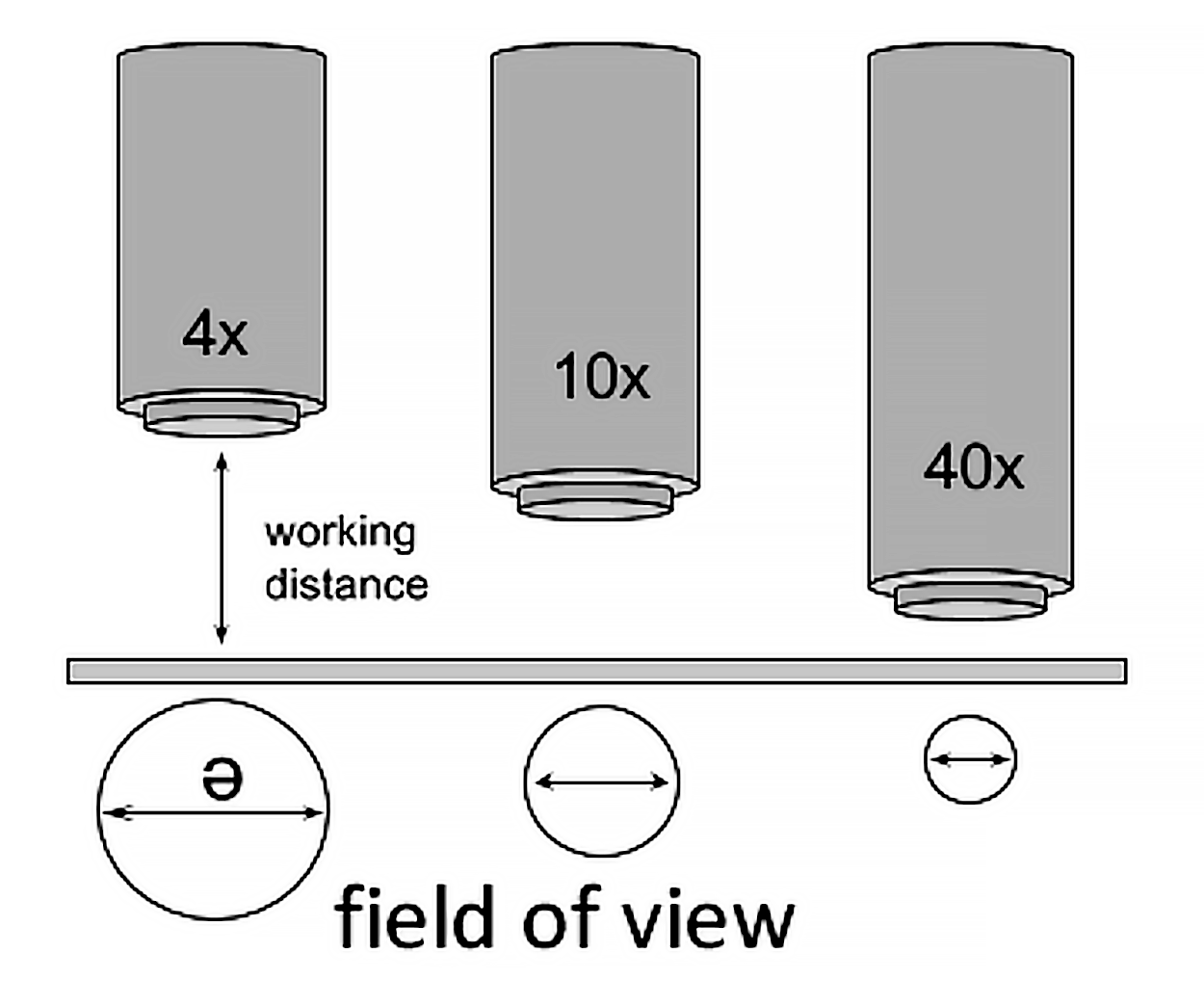
When viewing a slide on the microscope, you must be aware of specific concepts so that you can interpret your slide correctly. The field of view is the area of the slide that is visible through the microscope when you look into the eyepieces. The working distance is the distance between the slide on the stage and the tip of the objective lens. As you increase the magnification of your microscope, the field of view will decrease.
Brightfield microscopes are often parfocal, meaning that the image stays basically in focus as the objective is changed. This means that it is easier to find a specimen by scanning the slide at low magnification to quickly view a large area before raising the magnification.
Total magnification is how much larger the image appears when viewed through the eyepieces. To calculate the total magnification, you multiply the power of the ocular lens (printed on the side of the eyepiece) by the power of the objective lens (printed on the side of the lens).
EXAMPLE
If you are viewing a specimen in scanning view (4x) and your ocular lens is set at 10x, then your total magnification is 40x. This means the object you are viewing on the microscope is appearing 40 times bigger than it actually is.By measuring the diameter of the field of view when looking at a specimen on a microscope, you can calculate the actual size of objects too small to be seen with the naked eye. The field of view diameter is the distance from one edge of the field of view to the other edge of the field of view when passing through the circle's center point.
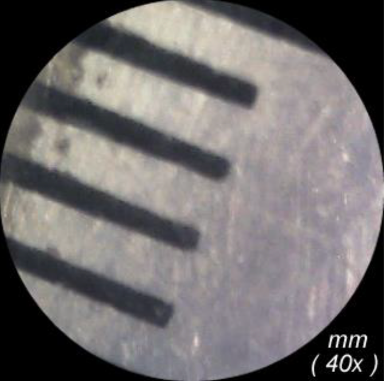
Using a clear millimeter (mm) ruler, you can count the number of gridlines to determine your measurement of the diameter in your field of view. In the image above, the diameter appears to be 4.5mm at 40x total magnification.
If you know the field of view diameter at one magnification (A), then you can predict the field of view diameter at another magnification (B). The formula is as follows:

IN CONTEXT
You are viewing a white blood cell (leukocyte) under the microscope. You are viewing the cell on the low objective (10x) and have an ocular lens power of 10x. The cell has a field of view diameter of 2mm. Assuming you are keeping the ocular lens power at 10x, what would be the field of view diameter if you viewed the cell under the high objective(40x)?
Field of View Diameter A (2mm) x Total Magnification A (100x) = 2mm x 100x = 200x
Total Magnification B is 400x because, remember, the total magnification is power of the ocular lens times power of the objective lens.

Field of View Diameter B is 0.5mm
Let's try another sample question:
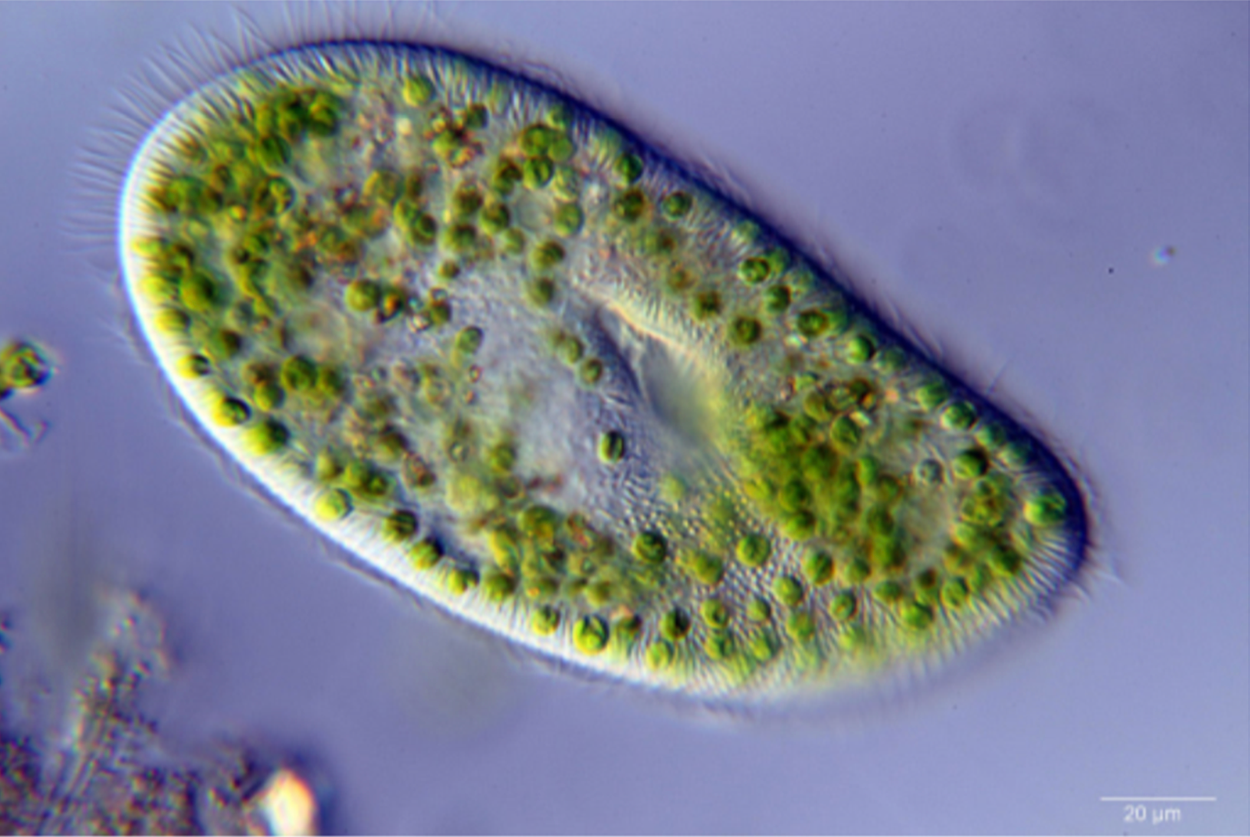
You are viewing a paramecium under the microscope. You are viewing the cell on high objective (40x) and have an ocular lens power of 10x. The cell has a field of view diameter of 1.5mm.
EXAMPLE
Assuming you are keeping the ocular lens power at 10x, what would be the field of view diameter if you viewed the cell under the scanning objective (4x)?
Use the formula:
Total Magnification = Ocular Power x Objective Power
Total Magnification is 10x x 40x = 400x and Total Magnification of B = 10x x 4x = 40x

Therefore, B = 15mm
Microscopes magnify objects that cannot be observed with the naked eye. Magnification is the ratio of the size of the image to the size of the object. The relationship between magnification, image size, and actual size is reflected in the following formula:

Note that magnification in this formula is equal to total magnification.
Using the formula stated above, we can predict the actual size of an object based on the microscope image size.
EXAMPLE
If magnification is 40x and image size is 40mm, then the Actual Specimen Size is 1mmThe depth of field of view is the distance between the nearest and farthest objects that are all within the field of view. The depth of field of view is essential for determining the layers of structures on 3D items like cells, where you might see various structures and organelles all in the same field of view.
To determine the depth of items within a field of view, use the scanning objective and find a point where objects overlap. Move your objective lens to the low power. Slowly move the fine focus in and out, noting which structure will be visible first. The item to focus clearly first is the top object. Others will be blurry. As you slowly focus again, other objects in the middle will become clearer. The last object to become clear is located at the bottom. Always make notes as you focus so you can determine the order of the structures within your slide.
You learned earlier that brightfield microscopes are widely used and produce a dark image on a bright background. Light passes through an objective lens and an ocular lens. As it passes through the specimen, the parts of the structure differentially transmit, absorb, reflect, and refract light. While the brightfield compound microscope will be the most common microscope that is used in laboratory classrooms, there are actually many different types of microscopes.
The stereo microscope is often referred to as a dissecting microscope. The stereo microscope provides magnification up to 300x. The stereo microscope is used to look at items that are too large to view on the compound microscope but too small to be viewed by the naked eye.
Unlike the stereo and compound microscope, which use regular light to refract an image, the confocal microscope uses a laser light to scan prepared specimens. Using a dichromatic mirror, the microscope reflects the image on a computer. Dichromatic means using two light wavelengths. This allows the viewer to create multiple scans and 3D images of the specimen. While the magnification of a confocal microscope isn’t any better than a compound microscope, the image resolution is much clearer.
In the twentieth century, new microscopes were developed that used non visible light. This opened up possibilities to view very small specimens. The smaller the wavelength, the higher the possible resolution.
The scanning electron microscope, or SEM, uses electrons rather than light to create an image from a sample. There is a special preparation that SEM specimens must undergo. All specimens must be vacuumed sealed, so they are dehydrated. Then, they must be coated with a conductive material, such as gold. The SEM produces a black-and-white 3D image with greater magnification than most microscopes. The SEM microscope is used frequently to view proteins, viruses, cell components, and spores.
Very similar to a SEM, the transmission electron microscope, or TEM, uses electrons to create an image of a specimen. The preparation for the TEM is labor intensive and the image is created in 2D instead of 3D. TEMs use a tungsten filament to produce a beam. The electrons from the beam accelerate through an electromagnetic field that passes through the specimen. An image is created from very fine samples of the material often less than 100nm. As the electrons pass through the sample they hit a screen or film to produce an image. TEMs create topographical, morphological, compositional, and crystalline images that allow researchers to examine structure and texture.
Computational Microscopy is a new emerging field of science, in which researchers use biological data to develop computer algorithms and models. This process helps express and understand the relationships and systems in biological science. With the speed and power of today’s computers, scientists can create models of scientific phenomena too small to be visualized with any of the microscopes we discussed today. The ability to visualize subcellular structures helps us better understand and predict diseases.
EXAMPLE
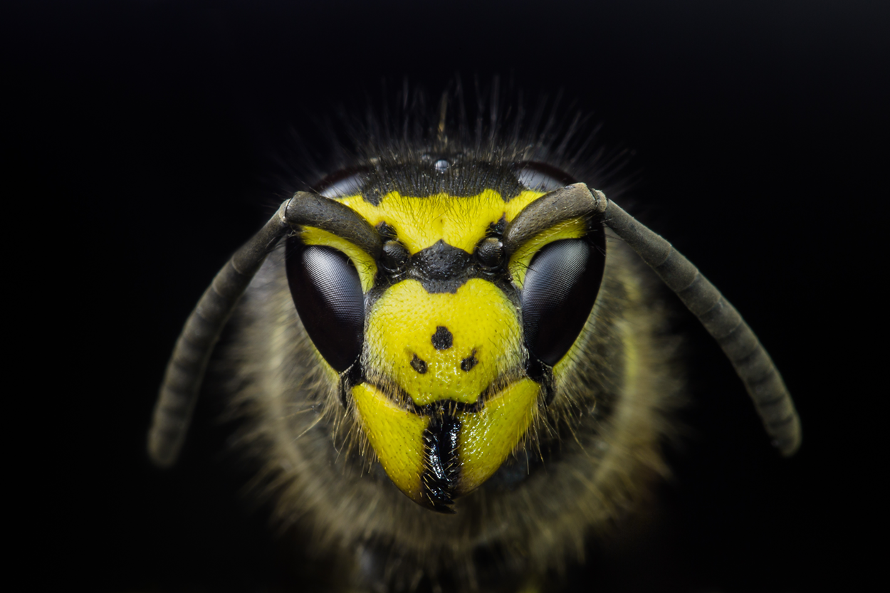
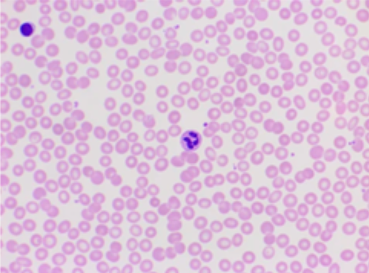
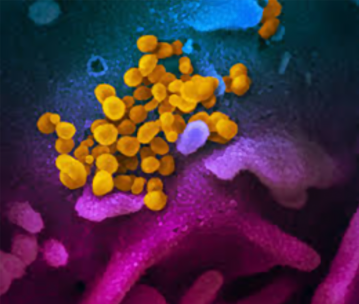
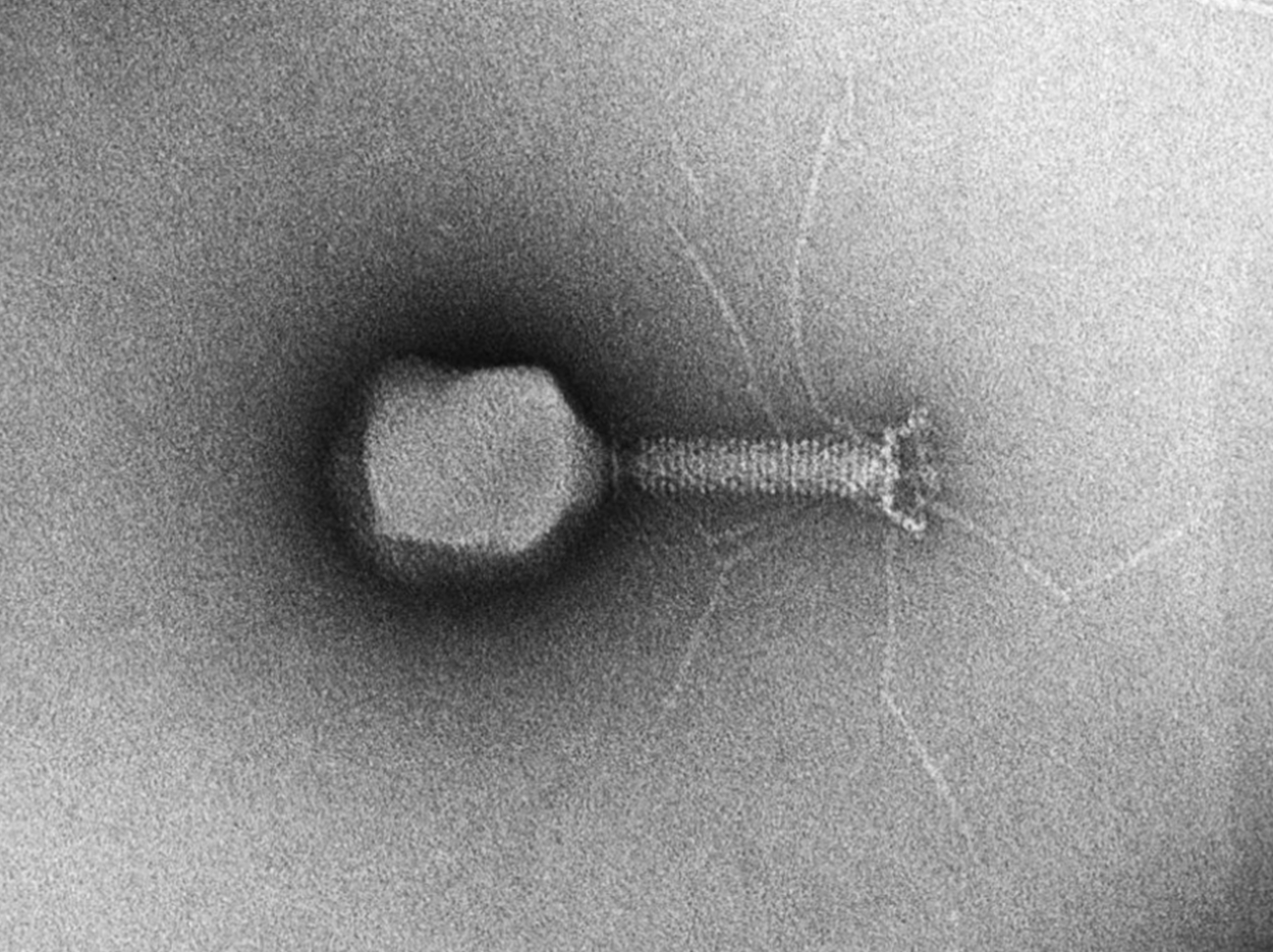
Molecular models have been used to help develop more effective pharmaceuticals and monitor viral outbreaks.The table and images below illustrate the power of the various microscopes and tools we use to visualize those items we cannot see with the naked eye. To help us understand the scale of the measurements, we will keep the units in millimeters for all the images in the table.
| Image Viewed | Tool Used and Description | Actual size |
|---|---|---|
|
Head of a yellow jacket Stereo Microscope |
9.5 mm |
|
Red and white blood cells Brightfield Compound microscope |
0.006 mm |
|
COVID virus (in yellow) Scanning Electron Microscope |
0.0001 mm |
|
T4 Bacteriophage Transmission Electron Microscope |
0.00003 mm |
|
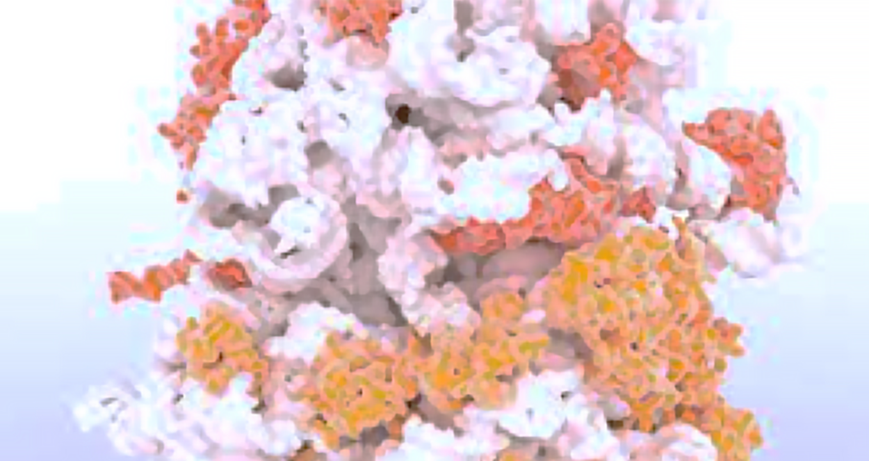
RNA and protein assembly Computational Microscopy |
0.000002 mm |
The following video shows the various types of microscopes introduced in this lesson: