Table of Contents |
In this lesson, we will look at the hardware tools that technicians use to make cables (well, more accurately, to attach connectors to lengths of cable) and to attach cables to patch panels. We’ll also discuss various hardware devices for testing cables.
A wire crimper, often simply called a crimper, is a handy tool found in most network technicians’ tool bags. Crimpers are primarily used for attaching connectors to network cables via a process known as—that’s right—crimping. Crimping involves using your hands to apply a certain amount of force to press some kind of metal teeth into the inner conductors of a cable. Before you can crimp a connector onto the end, you’ve got to strip the cable with a type of cable stripper (or snip) and then properly put the wires into the connector. The following figure shows what a cable stripper and snip looks like. This particular tool also includes a crimper.
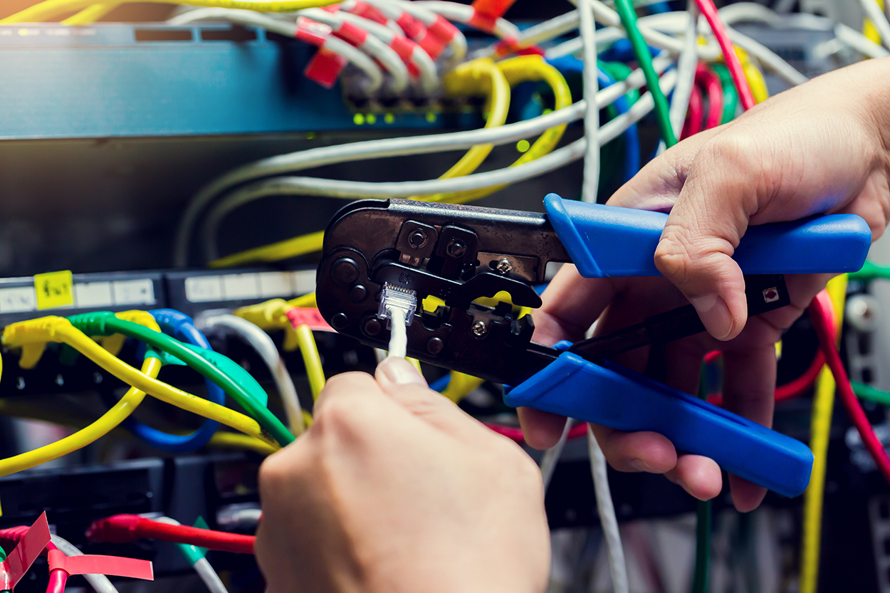
Network technicians often make patch cables with a crimper. They take a small piece of Category 5e unshielded twisted-pair (UTP), strip the cable, and crimp two RJ-45 ends onto it to create the cable. Snips will create the type of cable needed to connect a host to a wall jack connection, for example. There are strippers and crimpers for the other types of cable as well and even specialized crimpers for fiber-optic ends.
Most networks today are built using twisted-pair cable of some sort. This cable is usually terminated in wiring closets using a tool known as a punch-down tool. It’s called that because that’s exactly what the tool does—it punches down the wire into some kind of insulation displacement connector (IDC).
There are different types of punch-down tools. The most common is a punch-down with replaceable blades for the different types of connectors (either 66 or 110). The following figure shows an example of this type of punch-down tool.
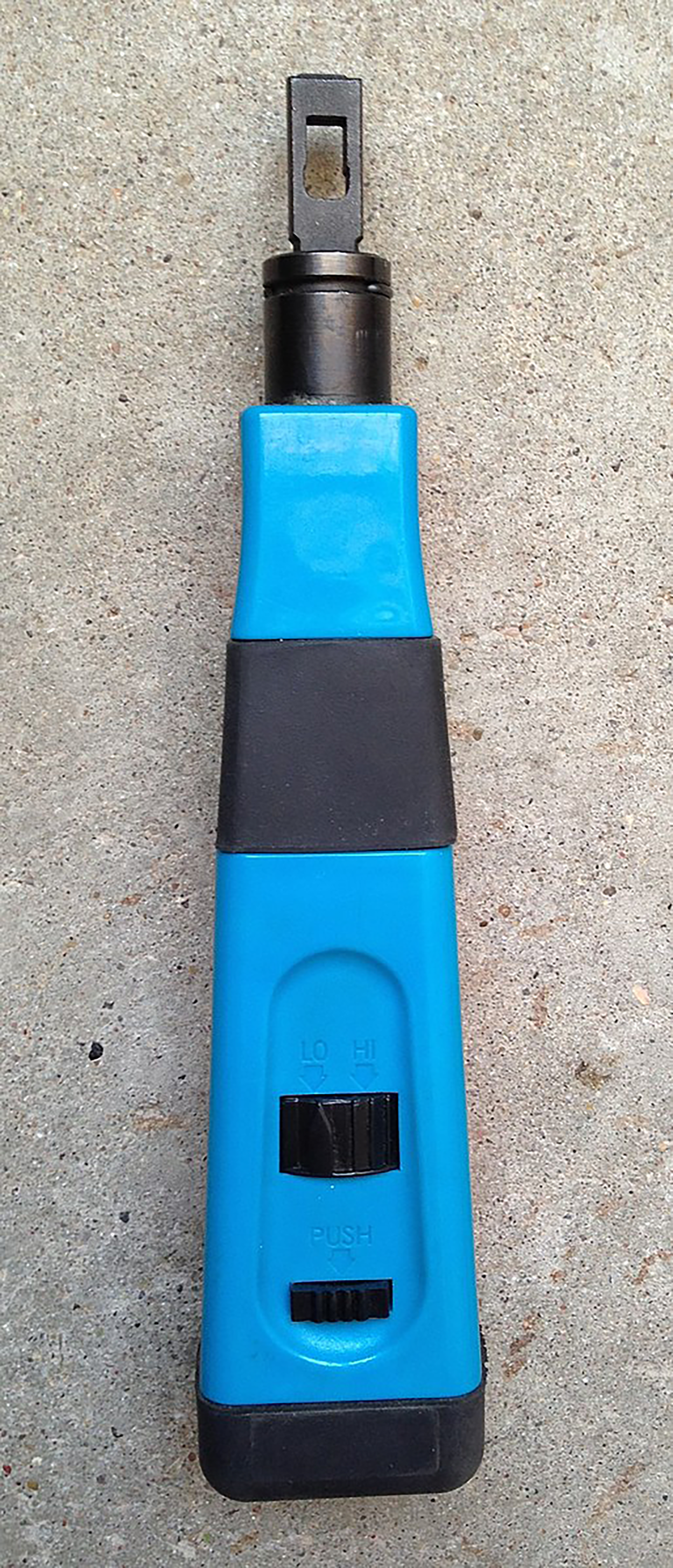
IDCs make contact by cutting through, or displacing, the insulation around a single conductor inside a twisted-pair cable.
As shown below, the punch-down tool pushes a conductor between the sides of a V-shaped groove inside an IDC, which in this example is a keystone connector, allowing the small metal blade inside the connector to make contact with the inner conductor deep inside the wire.
The best way to deal with a faulty cable installation is to avoid the problem in the first place by purchasing high-quality components and installing them carefully. Still, this isn’t a perfect world—no matter how careful you are, problems are bound to arise anyway. The tools covered in this tutorial can be used to test copper and fiber-optic cables at the time of their installation and afterward, if and when you need to troubleshoot cabling problems.
Other important considerations to keep in mind when selecting the types of tools you need are based on the test results required by the standards you’re using to certify your network and the capabilities of the people who will be doing the actual work. And don’t forget the potentially painful cost of some of them.
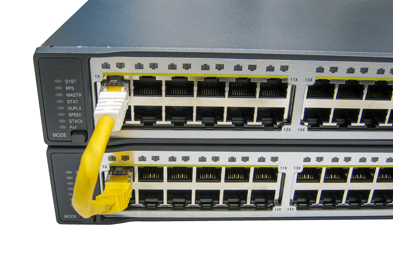
When troubleshooting a possible cable connectivity issue, it can be helpful to start by ensuring that the port itself is working. In other words, it might not be a cable issue at all, but a bad port that one end of the cable is connected to.
A loopback test is a diagnostic procedure in which a signal is transmitted and returned to the sending device after passing through all or a portion of a network or circuit. The returned signal is compared with the transmitted signal to evaluate the integrity of the equipment or transmission path. A computer needs a loopback plug that is inserted into a port in order to perform a loopback test. A loopback plug, as the name implies, has a circuit that circles back around on itself, feeding the output back into the port as input.
Loopback plugs are made for both Ethernet and fiber applications. The following images show an Ethernet loopback plug and a plug for fiber applications.
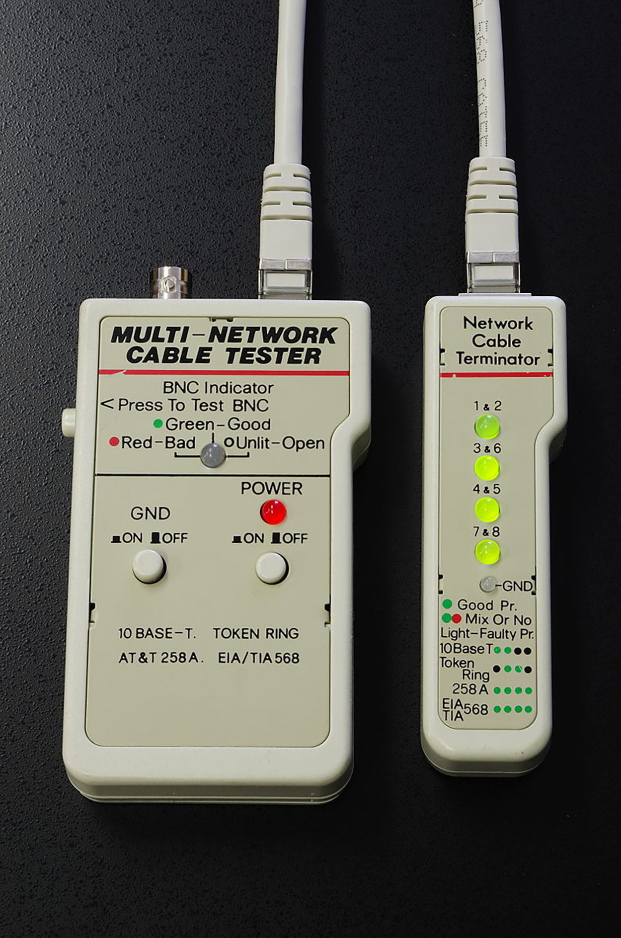
Cable-testing tools can range from simple, inexpensive mechanical devices to elaborate electronic testers that automatically supply you with a litany of test results in an easy-to-read pass/fail format. The following figure shows an example of an inexpensive cable tester for twisted-pair wiring testing. This little box can verify the connection through the cable and tell you if the cable is straight-through or crossover. It can also identify problems such as grounding issues. Sometimes the problem is not a complete lack of connectivity. Sometimes performance is slow, which can also be a cabling issue that a cable tester can identify.
A multimeter, or a multitester (also called voltmeter and ohmmeter), is a multitasking electronic measuring instrument. The average multimeter typically includes features like the ability to measure voltage, current, and resistance. Multimeters come in analog and digital versions, and they range from basic handheld devices useful for simple fault-finding and field-service work to more complex bench instruments that will give you measurements with a very high degree of accuracy.
Multimeters come in lots of flavors with different ranges of features and prices. Cheap ones cost less than $10, but the top-of-the-line models can cost you up to $5,000.
A wire-map tester is a device that transmits signals through each wire in a copper twisted-pair cable to determine if it is connected to the correct pin at the other end. Wire mapping is the most basic test for twisted-pair cables because the eight separate wire connections involved in each cable run are a common source of installation errors. Wire-map testers detect transposed wires, opens (broken or unconnected wires), and shorts (wires or pins improperly connected to each other). All of these problems can render a cable run completely inoperable.
A wire-map tester essentially consists of a remote unit that you attach to the far end of a connection and a battery-operated, handheld main unit that displays the results. Typically, the tester displays various codes that indicate the specific type of fault that it finds. You can also purchase a tester with multiple remote units that are numbered so that one person can test several connections without constantly traveling back and forth from one end of the connections to the other to move the remote unit.
Wire-map testing is nearly always included in high-end multifunction cable testers, but sometimes it is just not worth spending serious cash on a comprehensive device. Dedicated wire-map testers that run about $200–300 are relatively inexpensive options that enable you to test your installation for the most common faults that occur during installations and afterward. If, say, you’re installing voice-grade cable, a simple wire-mapping test is probably all that’s needed.
A continuity tester, or line tester, is a simpler and less expensive device than a wire-map tester; it is designed to check a copper cable connection for basic installation problems like opens, shorts, and crossed pairs. It will set you back only a few dollars, but such a device usually can’t detect the more complicated twisted-pair wiring faults. It’s still a nice option for basic cable testing, especially for coaxial cables that have only two conductors and so don’t easily confuse whoever is installing them.
Like a wire-map tester, a continuity tester consists of two separate units that you connect to each end of the cable you want to test. Most of the time, the two units can snap together for storage and easy testing of patch cables. But remember, a continuity tester simply tests continuity, equivalent to data at one bit per minute (or slower), and it cannot tell you whether or not a cable will reliably pass Ethernet data at network speeds. For that, you need a real cable tester that can test cables up to Gigabit speeds or higher.
A time-domain reflectometer (TDR) is a tool that finds and describes faults in metallic cables like twisted-pair and coaxial cables. The equivalent device for optical fiber is an optical time-domain reflectometer (OTDR).
A TDR works in the same basic way that radar does. It transmits a short rise time pulse along the conductor, and if it turns out to be of a uniform impedance and properly terminated, the entire transmitted pulse is absorbed in the far-end termination; no signal is reflected back to the TDR. Any impedance interruptions will cause some of the incident signal to be sent back toward the source, letting you know all is not well.
Any increases in the impedance create a reflection that reinforces the original pulse and decreases the impedance, thereby creating a reflection that opposes the original pulse. The resulting reflected pulse that is measured at the output/input to the TDR is displayed or plotted in measures of time. And because the speed of signal propagation is pretty consistent for a given type of transmission medium, the reading can also tell you about the cable length. Because of this sensitivity to any variation in impedance, you can use a TDR to verify the following things:
We use OTDRs to give us the following information:
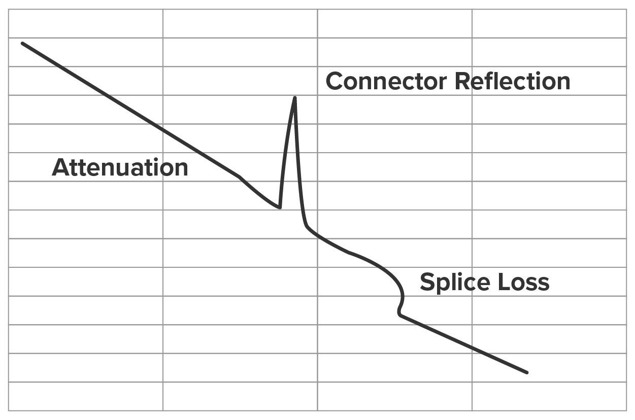
The spike in the above figure shows where a splice in the fiber is located, which has resulted in the signal being degraded. This is a very typical output. As the signal attenuates, you see a gradual but quick drop in decibels (dB). Any connector will actually show a reflection, which, as mentioned, shows up as a spike in the OTDR output. The connector then creates more attenuation and loss of more decibels. The more splices, the less distance you can run with fiber.
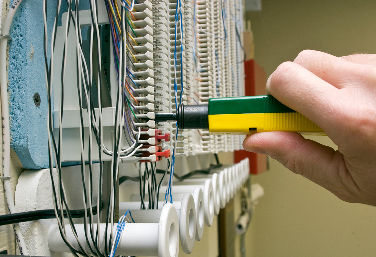
A dozen wires go into a wall, and a dozen wires come out of the wiring closet. But how can you identify which is which? A toner probe will help you sort them out. A toner probe, also called a tone generator, is a simple copper cable tester that is simple to use and can be used to trace a wire in a wall. It is a two-piece unit that’s basically a tone generator and probe, sometimes called a “fox and hound” wire tracer. This type of device consists of one part that you connect to a cable with a standard jack—or to an individual wire with alligator clips that transmit a signal over the cable or wire—and another part that’s a pen-like probe that emits an audible tone when it touches the other end of the cable, the wire, or even its insulating sheath.
Most often, you will use a toner probe to locate a specific connection in a punch-down block because (annoyingly) some installers run all the cables for a network to the central punch-down block without labeling them. They (or you, if you’re unlucky enough) then have to use a tone generator to identify which block is connected to which wall plate and label the punch-down block accordingly. This tool can identify a particular cable at any point between the two ends, and because the probe can detect the cable containing the tone signal through its sheath, it can help you to locate one specific cable out of a massive cable spaghetti bundle in a ceiling conduit or other type of raceway.
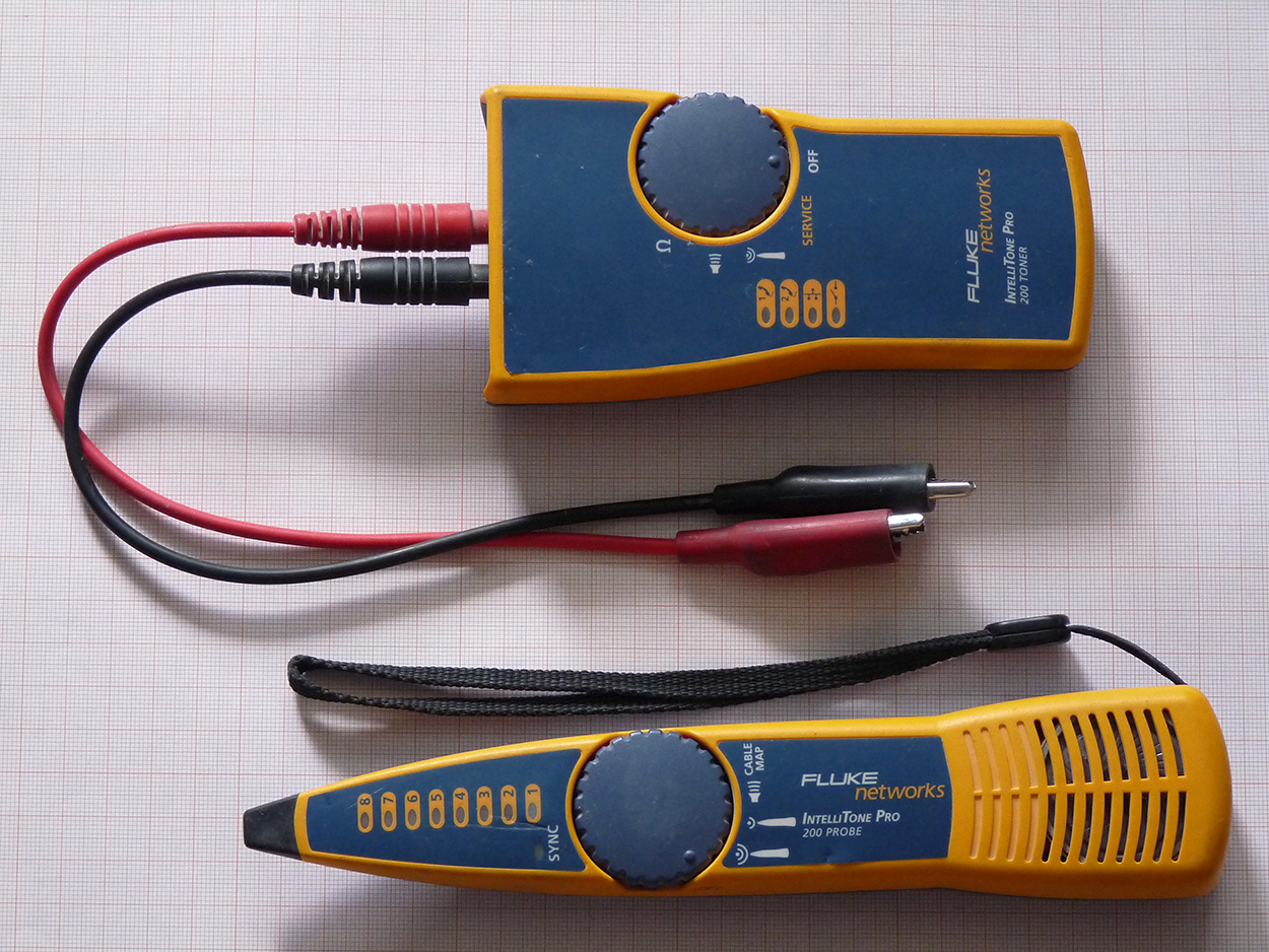
Just connect the tone generator to one end, and touch the probe to each cable in the bundle until you hear the tone. The following image shows a toner and the matching probe used to find the tone on the other end of the cable.
Also, by testing the continuity of individual wires using alligator clips, you can use a tone generator and probe to find opens, shorts, and incorrect wiring arrangements. An open wire won’t produce a tone at the other end, a short will produce a tone on two or more wires at the other end, and an improperly connected wire will produce a tone on the wrong pin at the other end. All that takes a really long time and is super tedious work. Worse, the whole process is almost as prone to errors as the cable installation itself. You have to either continually travel from one end of the cable to the other to move the tone generator unit or use a partner to test each connection, keeping in close contact using radios or some other means of communication to avoid confusion. So, considering the time and effort involved, investing in a wire-map tester is just a much more practical solution unless you’re numbingly bored or really easily amused.
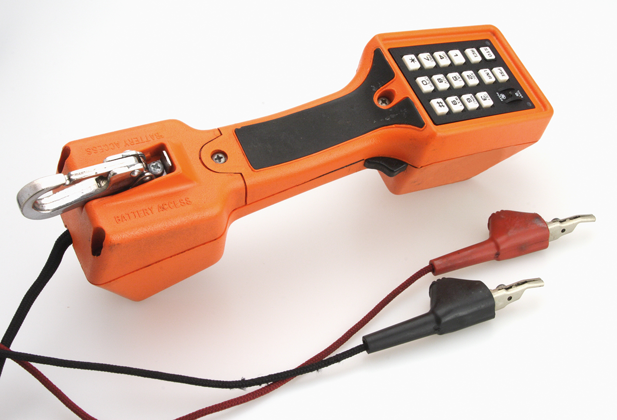
A butt set is essentially a portable telephone that enables you to test and monitor analog lines. The most common type, shown below, can both monitor and transmit. You see these all the time with telco guys up on the telephone poles. They use their butt sets to connect to telephone lines, test them, and even make phone calls.
Another handy tool that will take the place of a butt set is a hound. This non-canine device is nothing more than an inductively coupled amplifier with a small speaker in a handheld tool. It is used to monitor the audio on a given line to verify that you have the right pair before connecting it and is typically used with a toner probe. It will also monitor for noise.
Source: This content and supplemental material has been adapted from CompTIA Network+ Study Guide: Exam N10-007, 4th Edition. Source Lammle: CompTIA Network+ Study Guide: Exam N10-007, 4th Edition - Instructor Companion Site (wiley.com)