Table of Contents |
Networks and networking have grown exponentially over the last twenty years. They have had to quickly evolve to keep up with huge increases in basic user needs ranging from sharing data and printers to more advanced demands like videoconferencing. Unless everyone who needs to share network resources is located in the same office area, which is an increasingly uncommon situation, the challenge is to connect the sometimes large number of networks together so all users can share the networks’ resources.
Ethernet is a contention-based media-access method that allows all hosts on a network to share the same bandwidth of a link. Ethernet is popular because it is readily scalable, meaning that it is comparatively easy to integrate faster versions, such as Fast Ethernet and Gigabit Ethernet, into an existing network infrastructure. It is also relatively simple to implement in the first place, and with it, troubleshooting is reasonably straightforward.
In the following sections, we will also cover some basic terms used in networking with Ethernet technologies. Let’s start with collision domains.
The term collision domain is a particular area wherein one device sends a frame out on a network segment and every other device on that same physical network segment receives it. If two devices on one physical segment transmit at the same time, a collision occurs when each device’s signals interfere with another on the wire and forces the devices to retransmit later. Collisions may have a negative effect on network performance, so they are something we want to minimize.
A broadcast is a transmission address to all stations on a network. A broadcast domain refers to the set of all devices on a network segment that receive the broadcasts sent on that segment. Even though a broadcast domain is typically a boundary delimited by network routers, it can also reference a logical division of a network segment where all hosts can reach each other via a Layer 2 MAC address broadcast. We will cover collision domains and broadcast domains in more detail later in the course.
Ethernet networking uses Carrier Sense Multiple Access with Collision Detection (CSMA/CD), a media access control method that helps devices share the bandwidth evenly without having two devices transmit at the same time on the network medium. CSMA/CD was created to overcome the problem of those collisions that occur when frames are transmitted simultaneously from different hosts. Collision management is crucial because when a host transmits in a CSMA/CD network, all the other hosts on the network receive and examine that transmission. Only bridges, switches, and routers, but not hubs, can effectively prevent a collision from impacting the entire network.
So, how does the CSMA/CD protocol work? Let us start by taking a look at the diagram below, where a collision has occurred in the network.
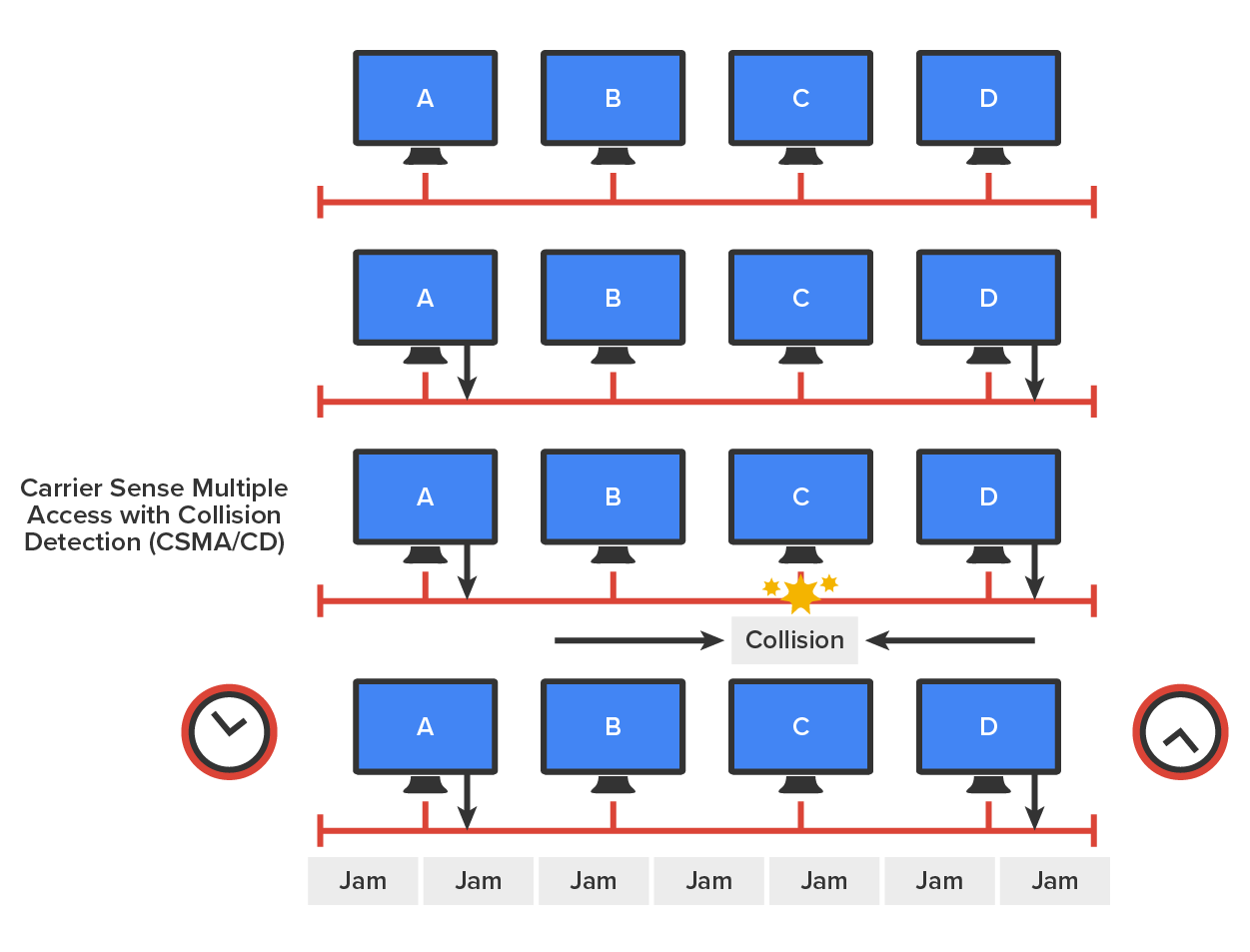
When a host wants to transmit over the network, it first checks for the presence of a digital signal on the wire, which is called “carrier”. If all is clear, meaning that no other host is transmitting, the host will then proceed with its transmission. The transmitting host constantly monitors the wire to make sure no other hosts begin transmitting. If the host detects a collision, it sends out an extended jam signal that causes all hosts on the segment to stop sending data.
The hosts respond to that jam signal by waiting a while before attempting to transmit again. A back-off algorithm determines when the colliding stations can retransmit. If collisions keep occurring after 15 tries, the hosts attempting to transmit will then stop transmitting that frame.
EXAMPLE
When a collision occurs on an Ethernet LAN, the following things happen:We have two ways to send analog and digital signals down a wire: broadband and baseband. We hear the term “broadband” a lot these days because that is pretty much what everyone uses at home. It allows us to have both our analog voice and digital data carried on the same network cable or physical medium. Broadband allows us to send multiple frequencies of different signals down the same wire at the same time, which is called frequency-division multiplexing, and to send both analog and digital signals.
Baseband is what all LANs use. This is where all the bandwidth of the physical media is used by only one signal. For example, Ethernet uses only one digital signal at a time, and it requires all the available bandwidth. If multiple signals are sent from different hosts at the same time, we get collisions.
Bit rate is a measure of the number of data bits (0s and 1s) transmitted in one second in either a digital or analog signal. A figure of 56,000 bits per second (bps) means 56,000 0s or 1s can be transmitted in one second, which we simply refer to as bps. Note the lowercase ‘b’ in bps; the uppercase in Bps means bytes per second.
In previous decades, we used the term baud rate frequently, but that was replaced by bps because it was more accurate. One baud is one electronic state change per second, for example, from 0.2 volts to 3 volts or from binary 0 to 1. However, since a single state change can involve more than a single bit of data, the bps unit of measurement has replaced it as a more accurate definition of how much data you are transmitting or receiving.
With electromagnetic radiation, radio waves, light waves, or even infrared waves make characteristic patterns as they travel through space. Patterns can have different wavelengths, as shown in the illustration below.
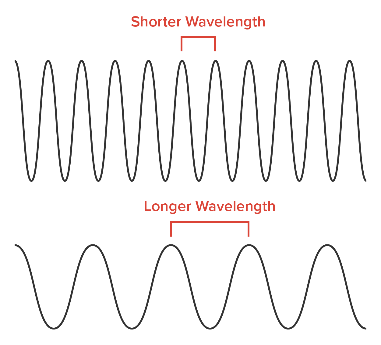
Each wave pattern has a certain shape and length. The distance between peaks (high points) is called wavelength. If two wave patterns are different, we would say they do not have the same wavelength and that is the way we tell different kinds of electromagnetic energy apart. We can use this to our advantage in electronics by sending traffic on different wavelengths at the same time.
Half-duplex Ethernet is defined in the original IEEE 802.3 Ethernet specification. Basically, when you run half-duplex, you are using only one wire pair with a digital signal either transmitting or receiving.
Here is how it works: If a host hears a digital signal, it uses the CSMA/CD protocol to detect collisions and to permit retransmitting if a collision does occur. Half-duplex Ethernet, typically 10BaseT, is only about 30 to 40% efficient because a large 10BaseT network will usually provide only 3 Mbps to 4 Mbps at most. Although it is true that 100 Mbps Ethernet can and sometimes does run half duplex, it is just not very common to find that happening anymore.
In contrast, full-duplex Ethernet uses two pairs of wires at the same time instead of just one wire pair like half duplex employs. Plus, full duplex uses a point-to-point connection between the transmitter of the sending device and the receiver of the receiving device, which in most cases is a switch. This means that with full-duplex data transfer, you not only get higher data-transfer speeds, but you also get collision prevention.
You do not need to worry about collisions because now it is like a freeway with multiple lanes instead of the single-lane road provided by half duplex. Full-duplex Ethernet is supposed to offer 100 % efficiency in both directions, for example, you can get 20 Mbps with a 10 Mbps Ethernet running full duplex or 200 Mbps for Fast Ethernet. But this rate is something known as an aggregate rate, which is the total amount of bandwidth available from all ports.
EXAMPLE
Ethernet can be used in many situations; here are some examples:When a full-duplex Ethernet port is powered on, it first connects to the remote end and then negotiates with the other end of the Fast Ethernet link. This is called an auto-detect mechanism. This mechanism first decides on the exchange capability, which means it checks to see if it can run at 10, 100, or even 1000 Mbps. It then checks to see if it can run full duplex, and if it cannot, it will run half-duplex instead. Hosts auto-detect by default both the speed (in Mbps) and the duplex type available, but you can manually set both the speed and duplex type on the network interface card (NIC), as shown here.
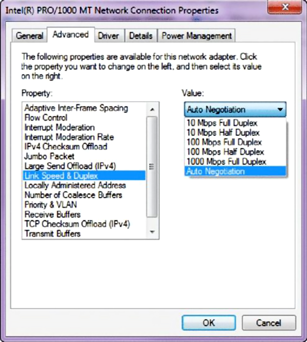
Today, it is pretty rare to go into a NIC configuration on a host and change these settings, but this example demonstrates that you can do that if you want.
Lastly, remember these important points:
Source: This content and supplemental material has been adapted from CompTIA Network+ Study Guide: Exam N10-007, 4th Edition. Source Lammle: CompTIA Network+ Study Guide: Exam N10-007, 4th Edition - Instructor Companion Site (wiley.com)