Table of Contents |
Ethernet at the Data Link Layer is responsible for Ethernet addressing, commonly referred to as a hardware address or MAC address. Ethernet is also responsible for framing packets received from the Network Layer and preparing them for transmission on the local network through the Ethernet contention media-access method known as CSMA/CD.
Understanding the differences between binary, decimal, and hexadecimal numbers and how to convert one format into the other is very important before we discuss the TCP/IP protocol stack and IP addressing later in the course.
So let us get started with binary numbering. It is pretty simple, really. Each digit used is limited to being either a 1 (one) or a 0 (zero), and each digit is called a bit (short for binary digit). Typically, you count either 4 or 8 bits together, with these being referred to as a nibble and a byte, respectively.
The table below shows the decimal values of each bit location in a nibble and a byte. Remember, a nibble is four bits and a byte is eight bits. In network addressing, we often refer to a byte as an octet.
EXAMPLE
When we get to the subnetting tutorial later in the course, you will see that we will use byte and octet interchangeably when discussing IP addressing.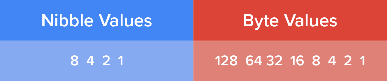
EXAMPLE
Another example for our nibble values is 1010, which means that the 8 bit and the 2 bit are set bits and equal a decimal value of 10. If we have a nibble binary value of 0110, then our decimal value is 6 because the 4 and 2 bits are set bits.
 .
. .
. .
.Hexadecimal is a number system with base sixteen, using the digits 0, 1, 2, 3, 4, 5, 6, 7, 8, 9, A, B, C, D, E, and F, most used in computing as a hexadecimal digit can represent four bits. Hexadecimal addressing is completely different from binary or decimal; it is converted by reading nibbles, not bytes. By using a nibble, we can convert these bits to hexadecimal simply. Remember, the hexadecimal addressing scheme uses only the numbers 0 through 9. And because the numbers 10, 11, 12, and so on can’t be used (because they are two-digit numbers), the letters A, B, C, D, E, and F are used to represent numbers 10, 11, 12, 13, 14, and 15, respectively.
The table shows both the binary value and the decimal value for each hexadecimal digit.
| Hexadecimal Value | Binary Value | Decimal Value |
|---|---|---|
| 0 | 0000 | 0 |
| 1 | 0001 | 1 |
| 2 | 0010 | 2 |
| 3 | 0011 | 3 |
| 4 | 0100 | 4 |
| 5 | 0101 | 5 |
| 6 | 0110 | 6 |
| 7 | 0111 | 7 |
| 8 | 1000 | 8 |
| 9 | 1001 | 9 |
| A | 1010 | 10 |
| B | 1011 | 11 |
| C | 1100 | 12 |
| D | 1101 | 13 |
| E | 1110 | 14 |
| F | 1111 | 15 |
So suppose you have something like this: 0x6A. (Some manufacturers put 0x in front of characters so you know that they are a hexadecimal value, while others just give you an h. It does not have any other special meaning.) What are the binary and decimal values? To correctly answer that question, all you have to remember is that each hexadecimal character is one nibble and two hexadecimal characters together make a byte. To figure out the binary value, first put the hexadecimal characters into two nibbles and then put them together into a byte. 6 = 0110 and A (which is 10 in decimal) = 1010, so the complete byte is 01101010.
To convert from binary to hexadecimal, just take the byte and break it into nibbles. Here is how you do that: Say you have the binary number 01010101. First, break it into nibbles—0101 and 0101—with the value of each nibble being 5 because the 1 and 4 bits are set. This makes the hexadecimal answer 0x55. And in decimal format, the binary number is 01010101, which converts to 64 + 16 + 4 + 1 = 85.
Okay, now try another example binary number:
Example A: 11001100
Our answer to Example A is 1100 = 12 and 1100 = 12 (therefore, it is converted to CC in hexadecimal). The decimal conversion answer is 128 + 64 + 8 + 4 = 204.
One more example, and then we need to get working on the Physical Layer. Suppose we are given the following binary number:
Example B: 10110101
In Example B, the hexadecimal answer is 0xB5 because 1011 converts to B and 0101 converts to 5 in hexadecimal value. The decimal equivalent is 128 + 32 + 16 + 4 + 1 = 181.
Now that you understand binary-to-decimal and hexadecimal address conversion, we can get into how Ethernet addressing works. It uses the Media Access Control (MAC) address burned into an Ethernet network interface card (NIC). The MAC, or hardware, address is a 48-bit (6-byte) address written in a hexadecimal format.
The illustration below shows the 48-bit MAC addresses and how the bits are divided.
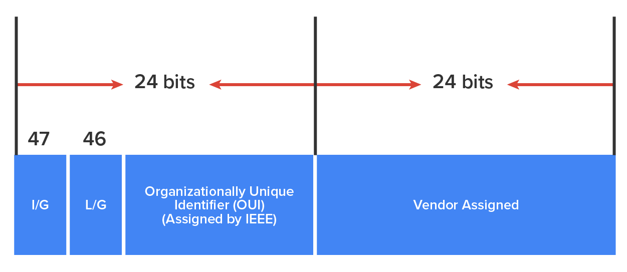
The organizationally unique identifier (OUI) is assigned by the Institute of Electrical and Electronics Engineers (IEEE) to an organization. It is composed of 24 bits, or 3 bytes. The organization in turn assigns a globally administered address (24 bits, or 3 bytes) that is unique to every adapter it manufactures. Look closely at the figure. The Individual/Group (I/G) address bit is used to signify if the destination MAC address is a unicast or a multicast/broadcast Layer 2 address. If the bit is set to 0, then it is an Individual MAC address and is a unicast address. If the bit is set to 1, it is a Group address and is a multicast or broadcast address. A unicast is a transmission addressed to one station, for example a laptop computer. A multicast is a transmission address to multiple stations, and a broadcast is a transmission addressed to all stations.
The next bit is the Local/Global bit (L/G). This bit is used to tell if the MAC address is the burned-in-address (BIA) or a MAC address that has been changed locally. You will see this happen when we get to IPv6 addressing. The low-order 24 bits of an Ethernet address represent a locally administered or manufacturer-assigned code. This portion commonly starts with 24 0s for the first card made and continues in order until there are 24 1s for the last (16,777,216th) card made. You will find that many manufacturers use these same six hexadecimal digits as the last six characters of their serial number on the same card.
The Data Link Layer is responsible for combining bits into bytes and bytes into frames within a unit of Ethernet data at Layer 2. Frames are used at the Data Link Layer to encapsulate packets handed down from Layer 3 (Network) for transmission on to the physical media at Layer 1 (Physical).
The function of Ethernet stations is to pass data frames between each other using a group of bits known as a MAC frame format. This provides error detection from a cyclic redundancy check (CRC), which provides error detection but not error correction. The 802.3 frame and the Ethernet frame formats are shown in the diagram below.
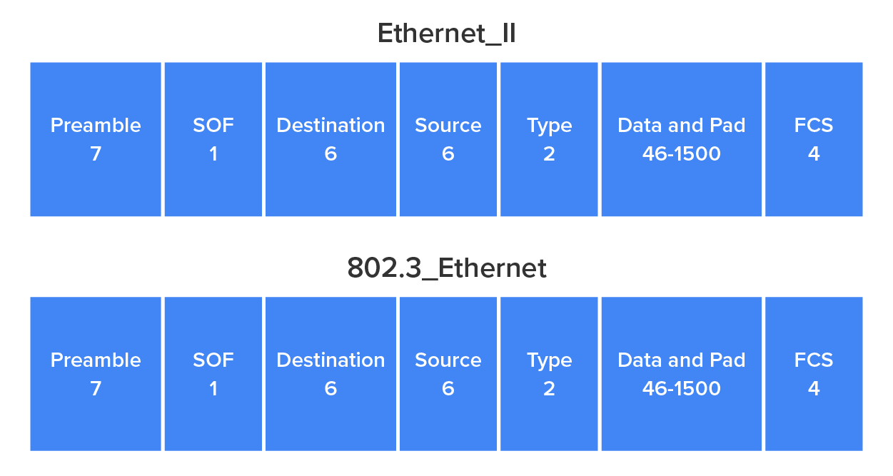
Following are the details of the different fields in the 802.3 and Ethernet frame types:
Preamble
The preamble is an alternating 1, 0 pattern that provides a clock at the start of each packet, which allows the receiving devices to clock the incoming bit stream. In simpler terms, the preamble alerts the Ethernet interfaces on the network that a transmission is being put on the physical medium.
Start of Frame Delimiter (SOF)/Sync
The start of a frame delimiter (SOF) is one octet that follows the preamble. The SOF is 10101011, where the last pair of 1s allows the receiver to come into the alternating 1, 0 pattern somewhere in the middle and still sync up and detect the beginning of the data.
Destination Address (DA)
The Destination Address (DA) is the MAC address of the network interface card on the computer that the frame is being sent to. The DA is used by receiving stations to determine whether an incoming packet is addressed to a particular host and can be an individual address or a broadcast or multicast MAC address. Remember that an Ethernet broadcast is all 1s (or Fs in hexadecimal) and is sent to all devices, but a multicast is sent only to a similar subset of hosts on a network.
Source Address (SA)
The Source Address (SA) is a 48-bit MAC address used to identify the transmitting device. Broadcast and multicast address formats are illegal within the SA field.
Length or Type
The Ethernet II (version 2) frame uses a Type field to identify the Network Layer protocol being carried in the data field of the frame. The original 802.3 used this field as Length, which indicated the size of the data field, but by itself it cannot identify the upper-layer routed protocol and must be used with a proprietary LAN protocol.
Data
This is a packet sent down to the Data Link Layer from the Network Layer. The size can vary from 64 to 1,500 bytes.
Frame Check Sequence (FCS)
The Frame Check Sequence (FCS) is a field that is at the end of the frame and is used to store the CRC.
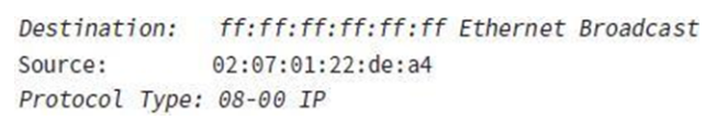
Let’s look at some frames captured by a network analyzer. You can see that the following frame has only three fields: Destination, Source, and Type, displayed as Protocol Type on this analyzer:
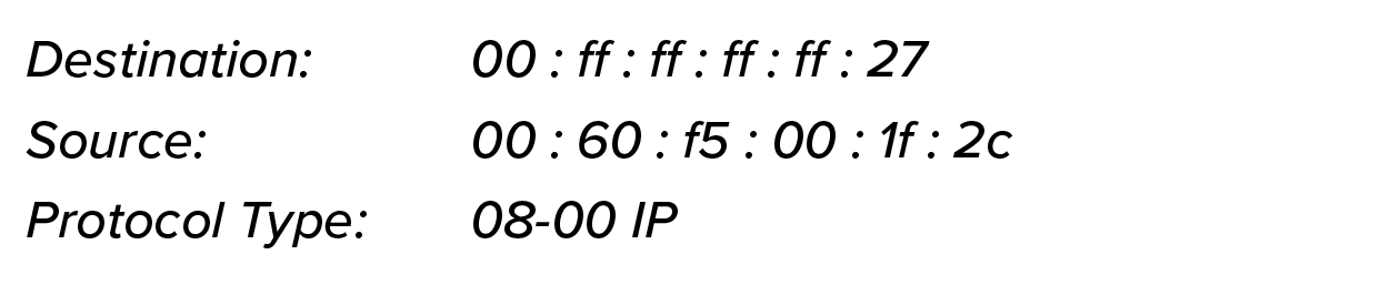
This is an Ethernet II frame. Notice that the Type field is IP, or 08-00 (mostly just referred to as 0x800) in hexadecimal.
The next frame has the same fields, so it must be an Ethernet II frame too.
Let us take a look at one more Ethernet frame. You can see that the Ethernet frame is the same Ethernet II frame we use with the IPv4 routed protocol. The difference is that the Type field has 0x86dd when we are carrying IPv6 data, and when we have IPv4 data, we use 0x0800 in the Protocol field:
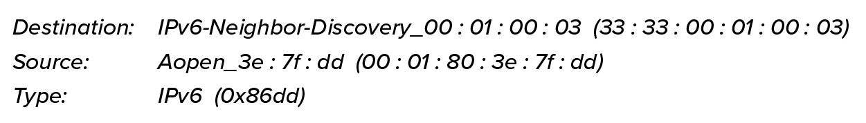
This is the beauty of the Ethernet II frame. Because of the Protocol field, we can run any Network Layer routed protocol and it will carry the data because it can identify that particular Network Layer protocol!
Source: This content and supplemental material has been adapted from CompTIA Network+ Study Guide: Exam N10-007, 4th Edition. Source Lammle: CompTIA Network+ Study Guide: Exam N10-007, 4th Edition - Instructor Companion Site (wiley.com)