Table of Contents |
The entity-relationship diagram (ERD) represents the relationships between entities (objects or concepts) in a database or system. ERDs provide a clear and concise view of data structure and help organize and flow data. We basically draw out the entire database—all the tables, their keys, and the relationships between the tables, including how they work and what is in them. It is sometimes referred to as an entity-relationship model (ERM).
As a simple example, let's explore how an ERD might express the relationships between entities in a university information system. Students, courses, and instructors are the main entities in the system. Students have attributes such as their StudentID, StudentName, Address, and EmailAddress. The Course entity has attributes such as CourseID, Title, and CreditHours, while the Instructor entity has attributes such as the InstructorID, InstructorName, and Office.
Relationships between entities are illustrated through lines. Using the Enrollment relationship, the Student entity is related to the Course entity, representing that a student can enroll in multiple courses. Instructor and Course entities also have a “Teaching” relationship, which indicates that an instructor can teach multiple courses, while several instructors can teach a course. Relationships like this are portrayed as many-to-many.
Many-to-many relationships are handled using associative entities—in other words, additional entities that exist only in order to associate data in one entity with data in another. In addition to capturing enrollment date and grade, the Enrollment entity represents the relationship between a Student and a Course. Teaching Assignments are associative entities between Instructors and Courses, storing details such as teaching assignment IDs and semesters.
ERDs provide a clear visual representation of university information system entities, attributes, and relationships. By providing stakeholders with a better understanding of the structure and relationships of the data, an ERD assists in system design and database creation, and ensures that student information is managed efficiently. As a result, instructors, students, and courses can be better managed.
There are three commonly used notation systems for representing relationships in an ERD:
Chen notation is a graphical representation technique widely used in entity-relationship modeling that emphasizes the clear and concise depiction of entities, relationships, and attributes. A rectangle represents an entity, a relationship is a diamond, and a line connects entities and relationships. It emphasizes cardinality and participation constraints as a means of conveying the nature and degree of relationships between entities. In addition, Chen notation provides a comprehensive overview of the data structure by depicting entity attributes within entity rectangles. Chen notation simplifies understanding complex data models through intuitive symbols and emphasizes relationships.
The concept of cardinality describes the numerical relationship between entities in a relationship. This term refers to the relationship between occurrences or instances of one entity and occurrences or instances of another entity.
Types of Cardinality:
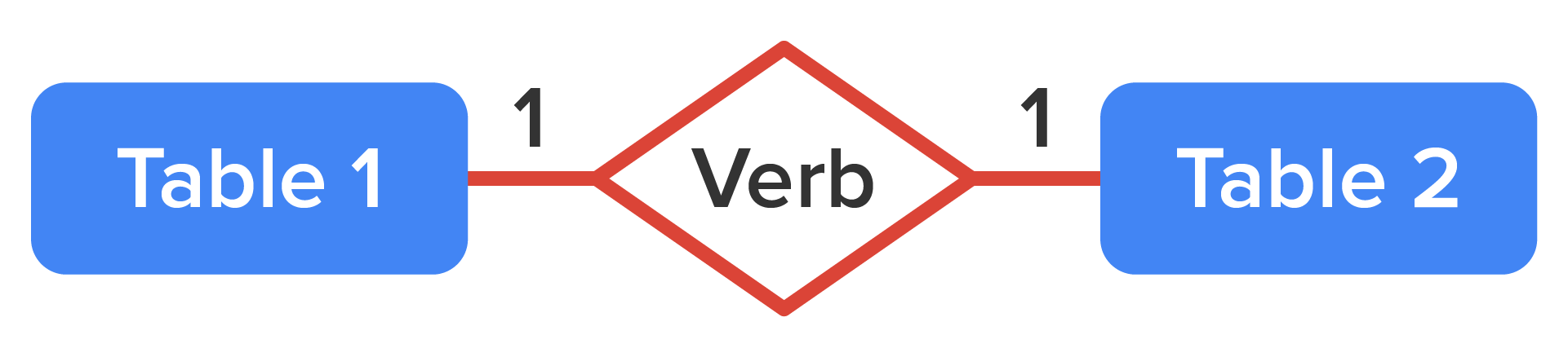
Chen notation for a one-to-one relationship between table1 and table2 would look like the following:
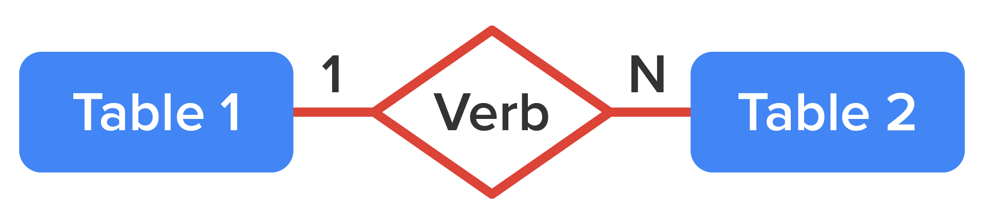
Chen notation for a one-to-many relationship between table1 and table2 would look like the following:
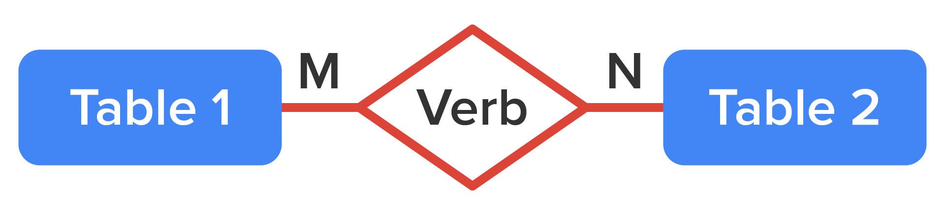
Chen notation for a many-to-many relationship between table1 and table2 would look like the following:
Crow's foot notation is a commonly used graphical representation technique in entity-relationship modeling where various symbols such as crow's feet, lines, and diamonds are used to represent cardinality, relationships, and attributes between entities. A crow's foot symbol (three lines) indicates a “many” side of a relationship, while a straight line indicates a “one” side. Diamonds represent relationships, and associations are represented by lines connecting entities. The data model is also presented with attributes within entity rectangles. As a method of conveying database structure and relationships, crow's foot notation is intuitive and widely adopted.
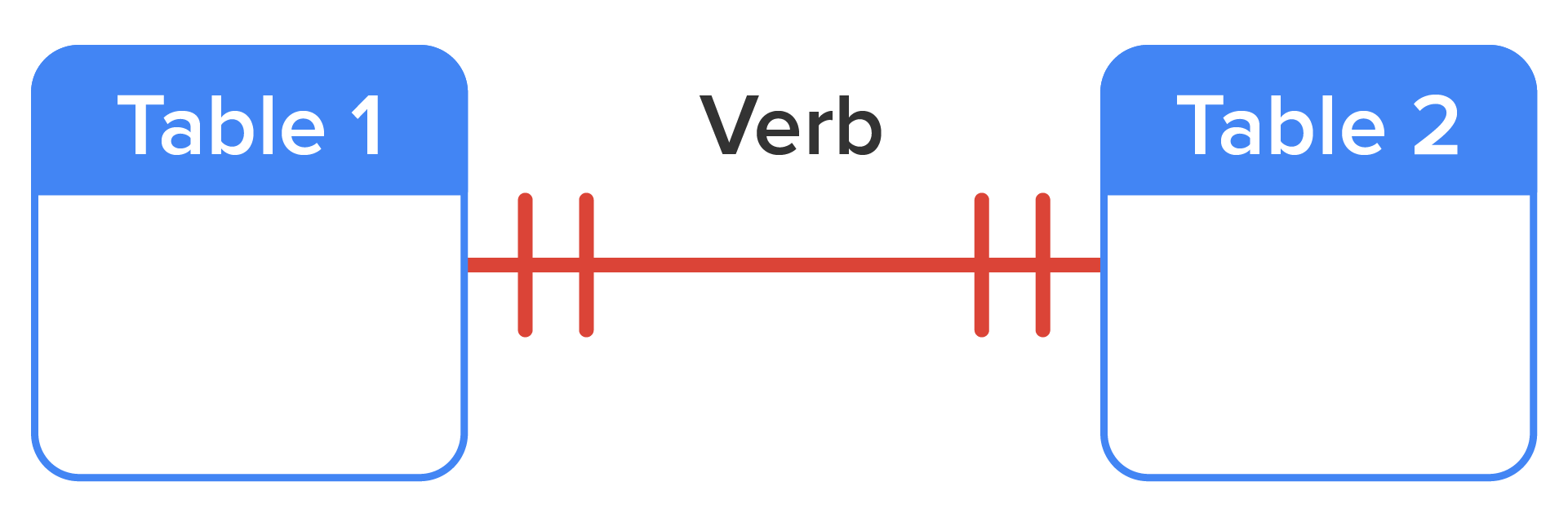
Crow’s foot notation (below) is slightly different from Chen notation in how relationships are identified. In Chen, you have 1:1 or 1:N, whereas in crow's foot, you have lines like -||- for a one-to-one relationship. Notice that the relationship name is placed above the relationship line instead of in a diamond in some cases, but you can use diamonds or names in crow's foot notation. The rectangles contain the table name at the top, and the attributes appear below the table name. The relationship line shows a short bisecting line segment if it is on the “one” side and a crow’s foot (two short bisecting lines) if it is on the “many” side.
Crow’s foot notation for a one-to-one relationship between table1 and table2 would look like the following:
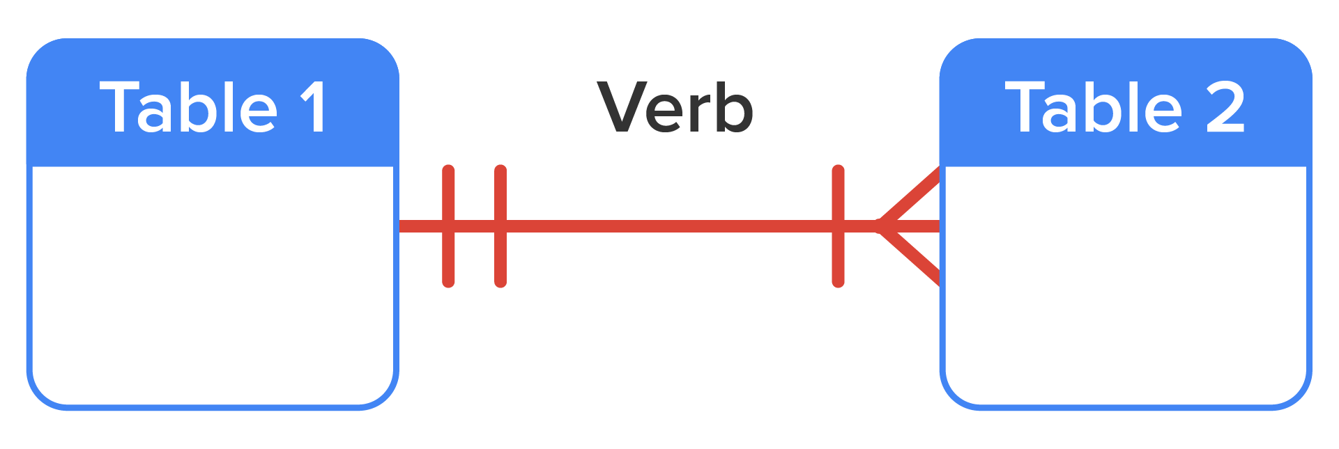
Crow’s foot notation for a one-to-many relationship between table1 and table2 would look like the following:
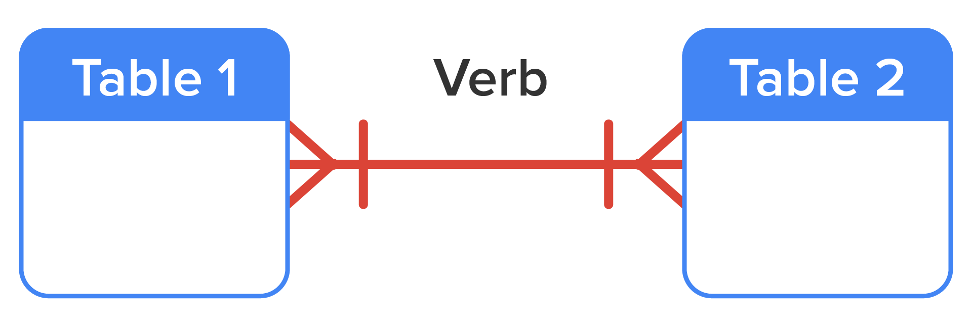
Crow’s foot notation for a many-to-many relationship between table1 and table2 would look like the following:
Unified Modeling Language (UML) class diagram notation can also be used to visually represent the structure, relationships, and constraints when designing a database system. A UML class diagram represents database entities as classes, with attributes and methods representing the associated data elements and operations. Lines and multiplicity notations indicate the cardinality of associations and relationships between entities. UML notation can easily represent a database's tables, foreign keys, and other database-specific elements. The database schema can be communicated and documented in a standard and intuitive manner, making it easy to understand, develop, and maintain the database system.
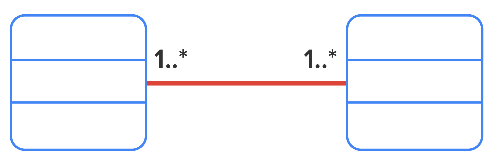
A class diagram (below) uses UML notation, which is similar to Chen notation. Notice that the class/entity name is still at the top of the rectangle, with attributes below it (and then methods/functionality below that). The connectivity is defined along the relationship line with symbols on each side, like 1..1 for one and 1..* for many.
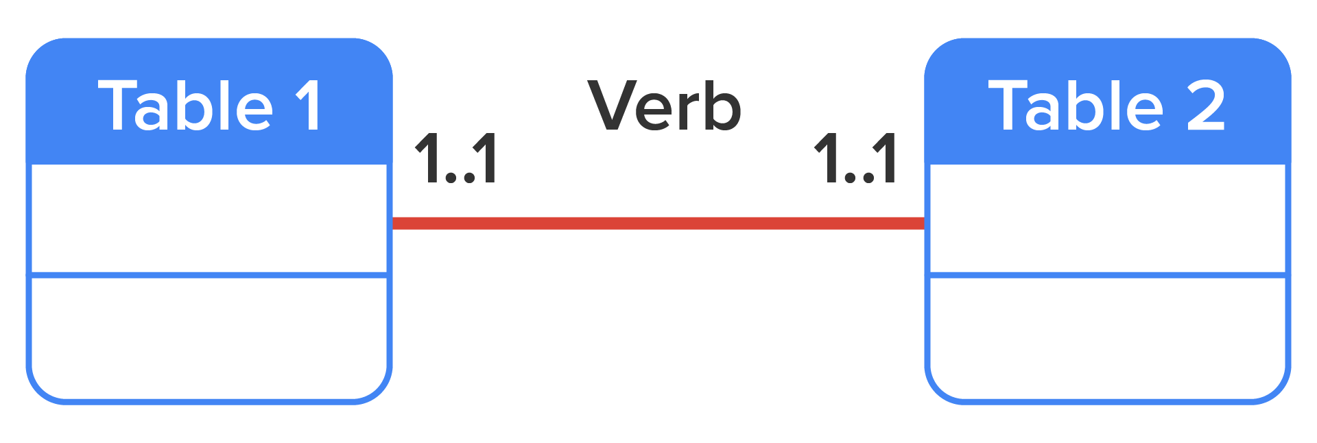
UML class diagram notation for a one-to-one relationship between table1 and table2 would look like the following:
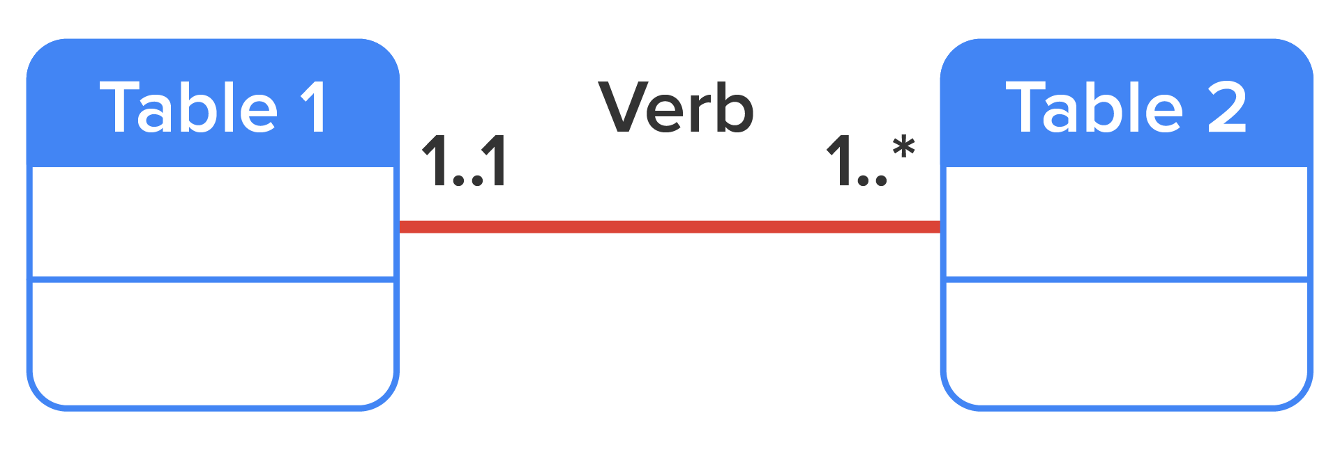
UML class diagram notation for a one-to-many relationship between table1 and table2 would look like the following:
UML class diagram notation for a many-to-many relationship between table1 and table2 would look like the following:
Source: THIS TUTORIAL WAS AUTHORED BY SOPHIA LEARNING. PLEASE SEE OUR TERMS OF USE.