Table of Contents |
The distance-vector routing algorithm passes its complete routing table contents to neighboring routers, which then combine the received routing table entries with their own routing tables to complete and update their individual routing tables. This is sometimes called routing by rumor because a router receiving an update from a neighboring router believes the information about remote networks without verifying for itself that the information is correct.
It is possible to have a network that has multiple links to the same remote network, and if that is the case, the administrative distance (AD) of each received update is checked first. If the AD is the same, the protocol will then have to use other metrics to determine the best path to use to get to that remote network.
Distance vector uses only hop count to determine the best path to a network. If a router finds more than one link with the same hop count to the same remote network, it will automatically perform what is known as round-robin load balancing.
It is important to understand what a distance-vector routing protocol does when it starts up. In the diagram below, the four routers start off with only their directly connected networks in their routing table. After a distance-vector routing protocol is started on each router, the routing tables are updated with all the route information gathered from neighboring routers.
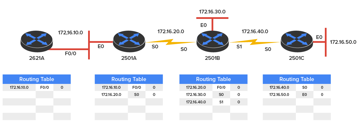
As you can see in the diagram above, each router only has the directly connected networks in its routing table. Also notice that their hop count is zero in every case. Each router sends out its complete routing table to each active interface, which includes the network number, exit interface, and hop count to the network.
In the diagram below, the routing tables are complete because they include information about all the networks in the internetwork. They are considered converged. Convergence is the state of a set of routers that have the same topological information about the internetwork in which they operate. The hop count for every directly connected network remains zero, but notice that the hop count is incremented by one each time the path completely passes through a router. So, for router 2621A, the path to the 172.16.10.0 network still has a hop count of zero, but the hop count for the path to network 172.16.20.0 is one. The hop count to networks 172.16.30.0 and 172.16.40.0 increases to two, and so on. Usually, data transmission will cease while routers are converging, which is a good reason in favor of fast convergence time! In fact, one of the main problems with RIP is its slow convergence time.
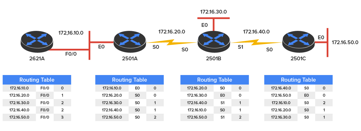
As you can see in the diagram above, once all the routers have converged, the routing table in each router keeps information about three important things:
Let’s start discussing dynamic routing protocols with one of the oldest routing protocols that is still in existence today.
RIP is a true distance-vector routing protocol. It sends the complete routing table out to all active interfaces every 30 seconds. RIP uses only one thing to determine the best way to a remote network—the hop count. And because it has a maximum allowable hop count of 15 by default, a hop count of 16 would be deemed unreachable. This means that although RIP works fairly well in small networks, it is pretty inefficient on large networks with slow WAN links or on networks populated with a large number of routers. Worse, this legacy protocol has a disadvantage of creating routing loops, which were somewhat kept in check by using things like maximum hop count. This is the reason why RIP only permits going through 15 routers before it will judge that route to be invalid. RIP is also slow at converging, which can easily cause latency in your network!
RIP version 1 (RIPv1) uses only classful routing, which means that all devices in the network must use the same subnet mask for each specific address class. This is because RIPv1 doesn’t send updates with subnet mask information in tow. RIP version 2 (RIPv2), discussed next, provides something called prefix routing and does send subnet mask information with the route updates. Doing this is called classless routing.
RIPv2 is mostly the same as RIPv1. Both RIPv1 and RIPv2 are distance-vector protocols, which means that each router running RIP sends out its complete routing tables to all active interfaces periodically. Also, the timers and loop-avoidance schemes are the same in both RIP versions. Both RIPv1 and RIPv2 are configured with classful addressing (but RIPv2 is considered classless because subnet information is sent with each route update), and both have the same AD (120).
The table below highlights the differences between RIPv1 and RIPv2.
| RIP v1 | RIP v2 |
|---|---|
| Distance vector | Distance vector |
| Maximum hop count of 15 | Maximum hop count of 15 |
| Classful | Classless |
| Broadcast based | Uses multicast 224.0.0.9 |
| No support for variable length subnet mask (VLSM) | Supports VLSM networks |
| No authentication | Allows for MD5 authentication |
| No support for discontiguous networks | Supports discontiguous networks (covered in the next section) |
Variable-length subnet masks (VLSMs) allow classless routing, meaning that the routing protocol sends subnet-mask information with the route updates. The reason it’s good to do this is to save address space. If we didn’t use a routing protocol that supports VLSMs, then every router interface, every device on the network, would have to use the same subnet mask.
As the name suggests, with VLSMs we can have different subnet masks for different router interfaces. Check out the diagram below to see an example of why classful network designs are inefficient.

Looking at this figure, you’ll notice that we have two routers, each with two LANs and connected together with a WAN serial link. In a typical classful network design example (RIP or RIPv2 routing protocol), you could subnet a network like this:
            192.168.10.0 = Network
            255.255.255.240 (/28) = Mask
Our subnets would be 0, 16, 32, 48, 64, 80, and so on. This allows us to assign 16 subnets to our internetwork. But how many hosts would be available on each network? Each subnet provides only 14 hosts. This means that with a /28 mask, each LAN can support 14 valid hosts—one LAN requires 25 addresses, so a /28 mask doesn’t provide enough addresses for the hosts in that LAN! Moreover, the point-to-point WAN link would consume 14 addresses when only 2 are required.
When all hosts and router interfaces have the same subnet mask, this is called classful routing. And if we want this network to be more efficient, we definitely need to add different masks to each router interface.
Another problem is that the link between the two routers will never use more than two valid host addresses, even though we have 14 host addresses available. This wastes valuable IP address space.
Now let’s take the diagram below that uses a classless design. In the previous example, we wasted address space; one LAN didn’t have enough addresses because every router interface and host used the same subnet mask.
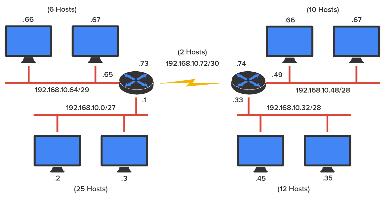
It is good to provide only the number of hosts needed on each router interface, meaning VLSMs. Remember that if a "classful routed network" requires that all subnet masks be the same length, then it follows that a "classless routed network" would allow us to use VLSMs.
So, if we use a /30 on our WAN links and a /27, /28, and /29 on our LANs, we’ll get 2 hosts per WAN interface and 30, 14, and 6 hosts per LAN interface. This solution provides just the right number of hosts on each LAN, so we still have room to add more WANs and LANs using this same network.
Remember, in order to implement a VLSM design on your network, you need to have a routing protocol that sends subnet mask information with the route updates. This would be RIPv2, EIGRP, or OSPF. RIPv1 and IGRP will not work in classless networks and are considered classful routing protocols.
Now, what’s a discontiguous network? It is one that has two or more subnetworks of a classful network connected together by different classful networks. The diagram below displays a typical discontiguous network.
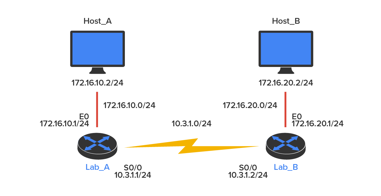
The subnets 172.16.10.0 and 172.16.20.0 are connected together with a 10.3.1.0 network. By default, each router thinks it has the only 172.16.0.0 classful network.
It’s important to understand that discontiguous networks just won’t work with RIPv1 at all. They don’t work by default on RIPv2 or EIGRP either, but discontiguous networks do work on OSPF networks by default because OSPF does not auto-summarize like RIPv2 and EIGRP.
Source: This content and supplemental material has been adapted from CompTIA Network+ Study Guide: Exam N10-007, 4th Edition. Source Lammle: CompTIA Network+ Study Guide: Exam N10-007, 4th Edition - Instructor Companion Site (wiley.com)