Table of Contents |
A network topology describes the shape of a network. The three primary shapes that are used to describe network topologies are a straight line, a circle, and a star. Networkers use the term “bus” when they mean a straight line and the term “ring” when they mean a circle.
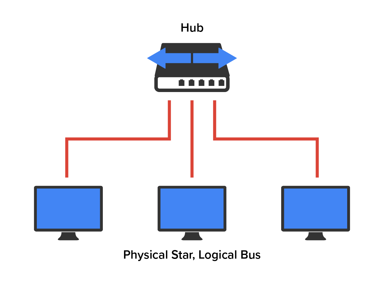
Physical topology defines the specific characteristics of a network, such as where all the workstations and other devices are located and the precise arrangement of all the physical media such as cables. A logical topology delineates exactly how data move through the network. A particular network can actually have physical and logical topologies that are very different. In fact, almost all LANs today have a star-wired bus topology, which means the cabling is a physical star, but the logic for media access control logically acts as if it were using an Ethernet bus.
A bus is the most basic topology.
A physical bus topology is just a straight cable installed in a workspace that has computers connected to it. The original Ethernet LAN networks were built using a physical bus topology of coaxial cables, although modern Ethernet networks are not constructed this way anymore. Physical buses are legacy. The original Thicknet was indeed pretty much a straight line with very little ability to bend, because it was stiff and bulky. Thinnet buses were made of thinner cable and had a higher bend radius (the ability to be bent), but they were also laid out more or less in a straight line.
The benefits of using a bus topology are that it’s easy to install and not very expensive, partly because it doesn’t require as much cable as the other types of physical topologies. It also has some drawbacks.
EXAMPLE
It is hard to troubleshoot, change, or move, and it does not offer much fault tolerance, because computers are connected to a single cable. This means that any break in the cable will bring the whole network down.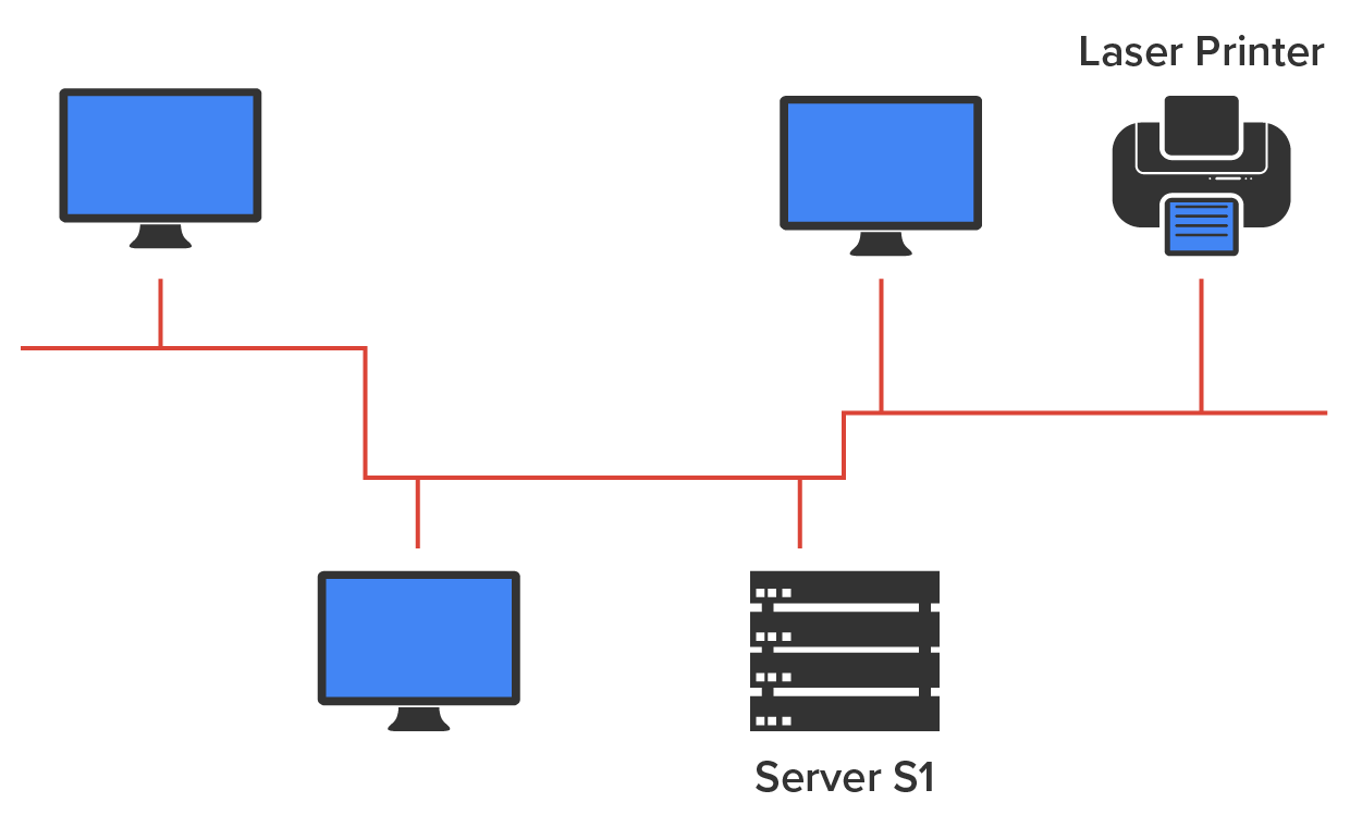
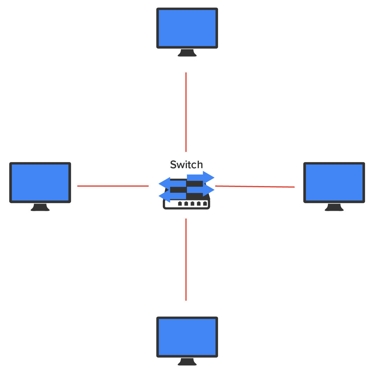
A star topology’s computers are connected to a central point with their own individual cables or wireless connections. You will often find that central spot inhabited by a device like a hub, a switch, or an access point.
A star topology offers several advantages over a bus topology. Therefore, it is more widely used even though it requires more physical media, because each device has its own dedicated cable connected to the hub or switch.
IN CONTEXT
One of its best features is that each computer or network segment is connected to the central device individually. If the cable fails, it will only bring down the machine or network segment related to the point of failure. This makes the network much more fault tolerant and much easier to troubleshoot. Another great thing about a star topology is that it’s a lot more scalable, and all you have to do if you want to add to it is run a new cable and connect it to the machine at the core of the star.
Although it is called a star topology, this topology looks a lot like a bike wheel with spokes connecting to the hub in the middle of the wheel and extending outward to connect to the rim. And just like the bike wheel, it is the hub device at the center of a star topology network that can give you the most grief if something goes wrong with it. If that central hub happens to fail then the whole network goes down.
A star topology has its pros and cons. But the good features far outweigh the bad, which is why people often opt for a star topology.
| Benefits | Disadvantages |
|---|---|
|
|
The following is an example of a star topology:
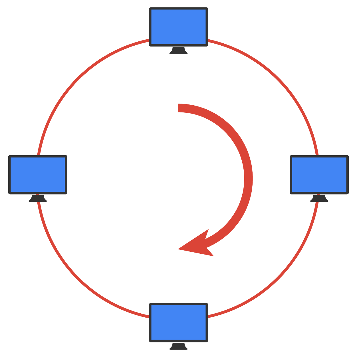
Another type of network topology is ring topology. In a ring topology, each computer is directly connected to other computers within the same network. The network’s data flow from computer to computer back to the source. The network’s primary cable forms a ring.
A ring topology has a lot of the same challenges as those found in networks with a bus topology. If you want to add to the network, you have no choice but to break the cable ring. This action is likely to bring down the entire network. This is a major reason a ring topology is not used much anymore. It is also expensive, because it requires several cables to connect each computer. It is also hard to reconfigure. It is not fault tolerant, unless you build a double ring and connect each computer to both. You may still find a physical ring topology used for WAN technology. However, you will not find many LANs in physical rings anymore.
Full mesh topology is another form of network topology, in which there is a path from every machine to every other machine in the network. This provides the most fault-tolerant network design. A full mesh topology is not used in LANs very often. It is very expensive to construct and maintain. You may have used a modified version, known as a hybrid or partial mesh topology. Partial mesh technology is used in WANs, including the internet. Networks with a hybrid mesh topology will have quite a few connections between certain places to create redundancy (backup).
The following is an example of a full mesh topology:
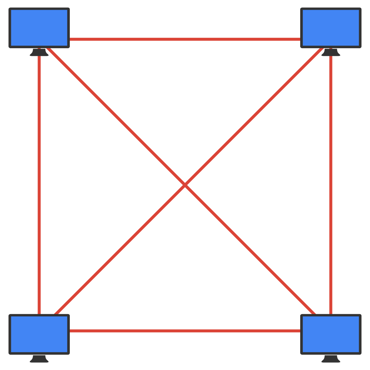
As you can see, mesh networks become more complex as both the wiring and the connections multiply.
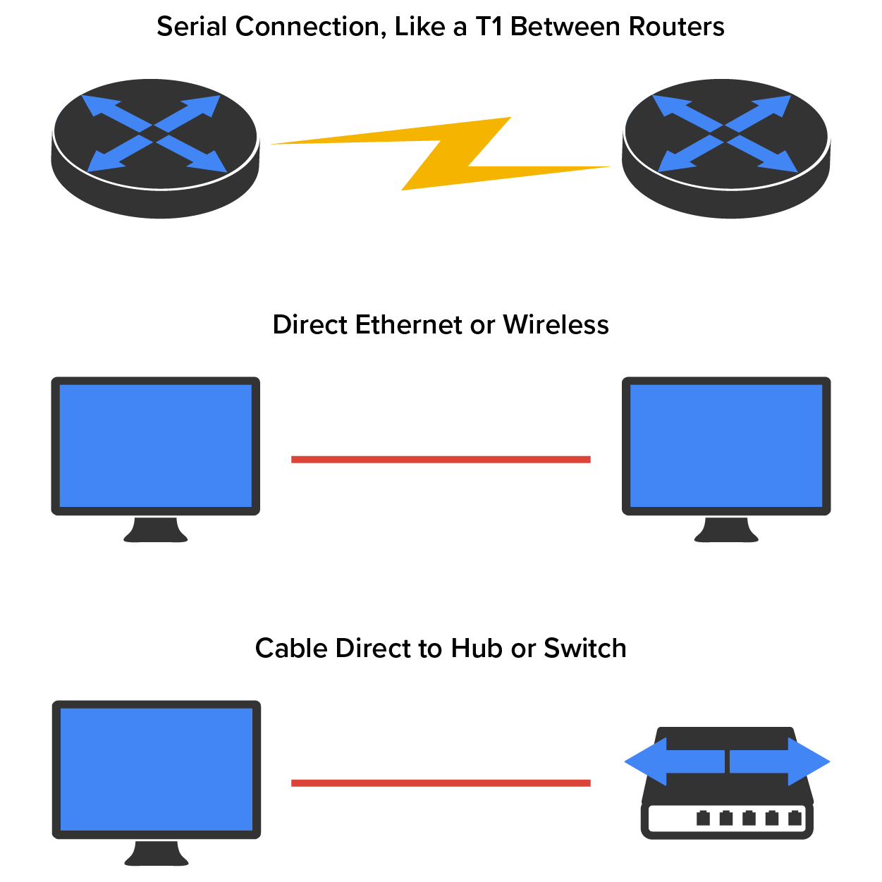
A point-to-point topology has a direct connection between two routers or switches, which provides one communication path. The routers in a point-to-point topology can be linked by a serial cable. Alternatively, they may be located far apart and connected via a circuit leased from a telecommunications service provider. Point-to-point networks are used in many of today’s WANs and are the simplest possible topology.
The following image has a lightning bolt and a couple of round icons with some arrows projecting from them. The two round icons with the radiating arrows represent our network’s two routers, and the lightning bolt represents a WAN link. These icons are industry conventions and will be used throughout this course. Many diagramming software applications, like MS Visio, include a library of icons for making network diagrams.
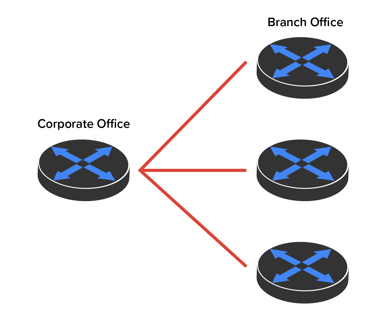
A point-to-multipoint topology is a network topology that consists of one point of connection to multiple points of connection.
EXAMPLE
A point-to-multipoint topology could have multiple connections between an interface on one router and multiple destination routers. Each of the routers and every one of their interfaces involved in the point-to-multipoint connection are part of the same network.The following is an example of point-to-multipoint technology:
The final network topology covered in this tutorial is the hybrid topology. A hybrid topology is a combination of two or more types of physical or logical network topologies working together within the same network.
The following is an example of a star-wired bus:
As you consider which type of network topology is best suited for your application, there are other realities you will need to address. Each network topology has pros and cons to implementing it. Some topologies are too expensive to be used. Others are easy to use and maintain, while others are not. Various topologies meet or do not meet fault-tolerance requirements. Finally, each topology will have its own security limitations.
EXAMPLE
Buses are easy to install, but they are not fault tolerant. A single ring is not fault tolerant, but a double ring is. Both physical buses and rings are legacy in most enterprise networks. The term “legacy” refers to an older hardware or software technology that may not be supported by the vendor. The star topology is highly fault tolerant, is easy to troubleshoot, and often uses inexpensive unshielded twisted pair (UTP) cable.Care should be taken to ensure that the most appropriate topology is used within the business realities you face.
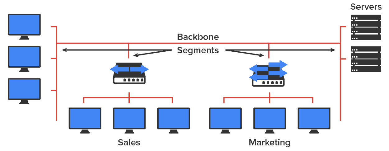
Today’s networks can be complicated, so it is necessary to have a standard way of communicating with each other the parts of the network that are being referenced. For this reason, networks are divided into different parts called backbones and segments. The network backbone is like that of a human.
As you can imagine, being such an important nerve center, the backbone must use a fast technology, often Gigabit Ethernet. To optimize network performance, all of the network’s servers and segments are connected directly to the network backbone.
Source: This content and supplemental material has been adapted from CompTIA Network+ Study Guide: Exam N10-007, 4th Edition. Source Lammle: CompTIA Network+ Study Guide: Exam N10-007, 4th Edition - Instructor Companion Site (wiley.com)