Table of Contents |
Wireless local area networks (WLANs) are widely popular in both SOHO and enterprise environments, because they provide end users with mobility, which is the freedom to move around an area while maintaining a connection to a network. This section will focus on two common components of wireless networks: access points and wireless range extenders.
Access points (APs), like wireless networks, help users access a network. APs could be computers or mobile devices, and soon home appliances will have IP addresses and be able to communicate wirelessly. The ease of communicating on a network using a wireless access point (WAP) instead of having to use an Ethernet cable enables end-user mobility.
The diagram below shows how an AP would look in a small network, such as a home.
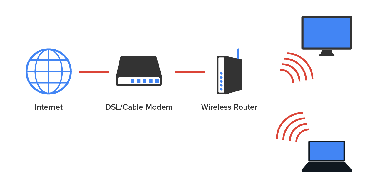
An AP is a device that permits wireless devices to connect to a network. The wireless client modulates a digital signal to an analog signal, which the AP can read and demodulate back to a digital signal. A WAP is the wireless equivalent of a switch or router, and it provides the same services to the network. An AP may operate at half-duplex, but some wireless standards provide full-duplex-type connectivity. Currently, a wireless host typically operates at a lower speed, and with less security, than a wired Ethernet network connection.
Wireless range extenders are used to extend wireless signals far from the AP. These are radios with antennas that receive the wireless signal from an AP and then transmit it to an area not covered by the AP. These devices should be placed so there is at least a 15% overlap of the coverage areas of the AP and the extender.
In both wireless and wired environments that are shared media, frames from multiple devices could collide and destroy the data. Both wired and wireless environments use a media access control protocol to arbitrate access to the medium to help prevent collisions or, at the least, recover from them when they occur. A media access control protocol is a set of rules that enables multiple devices to share the physical medium of a network. In the following sections, we will look at the method used in each environment.
When the device transmits the frame onto a wireless network, carrier-sense multiple access with collision avoidance (CSMA/CA) or the contention method is used. The method starts with a check of the medium (in this case, a check of the radio frequency) for activity called physical carrier sense. If the medium is not clear, the station will implement an internal countdown mechanism called the random back-off algorithm. This counter will have started counting down after the last time this station was allowed to transmit. All stations will begin the countdown on their own individual timers. When a station’s timer expires, it is allowed to send the information. If the physical carrier is clear and the countdown timer is at zero, the station will send.
The frame will go to the AP. The AP will acknowledge the reception of the frame. If the frame is destined for another wireless station located on this WLAN, the AP will forward the frame to it. When this occurs, the AP will follow the same CSMA/CA contention method to get the frame onto the wireless medium. Because it is impossible for wireless stations to detect collisions, another contention method is required to arbitrate access to the network. The method is called carrier-sense multiple access with collision avoidance (CSMA/CA).
Describing CSMA/CA Operation
CSMA/CA operation requires a more involved process of checking for existing wireless traffic before a frame can be transmitted wirelessly. The stations (including the AP) must also acknowledge all frames.
When you consider that this process has to occur for every single frame and that there are many other frame types used by the AP to manage the other functions of the network that also compete for air time, it is no wonder that the actual throughput on a wireless LAN is typically about half the advertised rate.
When the device transmits the frame onto a wired network, the CSMA/CD contention method is used. This method is more efficient, because it is possible for wired computers to detect collisions, whereas wireless stations cannot. When a host’s or router’s interface needs to send a frame, it checks the wire; if no traffic is detected, it sends the frame without checking a random back-off timer.
However, it continues to listen, and if it detects that a collision has occurred, it sends out a jam signal that requires all stations to stop transmitting. Then, the two computers that were involved in the collision will both wait a random amount of time (that each will arrive at independently) and will resend the frame. So, instead of using a random back-off algorithm every time a transmission occurs, Ethernet uses its ability to detect collisions and uses this timer only when required, which makes the process more efficient.
Describing CSMA/CD Operation
The contention method used in wired Ethernet networks is called carrier-sense multiple access with collision detection (CSMA/CD). It has mechanisms that help minimize but not eliminate collisions.
Even though we are going to get into the finer points of Dynamic Host Configuration Protocol (DHCP) later in the course, it may be helpful to get some basic insight into this server service here. DHCP servers automatically assign IP addresses and other information to a host computer. An alternative method known as static IP addressing requires each host to be configured manually. DHCP works well in any network environment and allows all types of hardware to be employed as a DHCP server, including switches, hubs, bridges, repeaters, and routers.
DHCP works like this: A DHCP server receives a request for IP information from a DHCP client using a broadcast. The administrator configures the DHCP server with a pool of addresses that it uses for this purpose.
If the DHCP server is not on the same segment as the DHCP client, the server will not receive the broadcast, because by default, routers will not forward broadcasts, as shown in the diagram below.
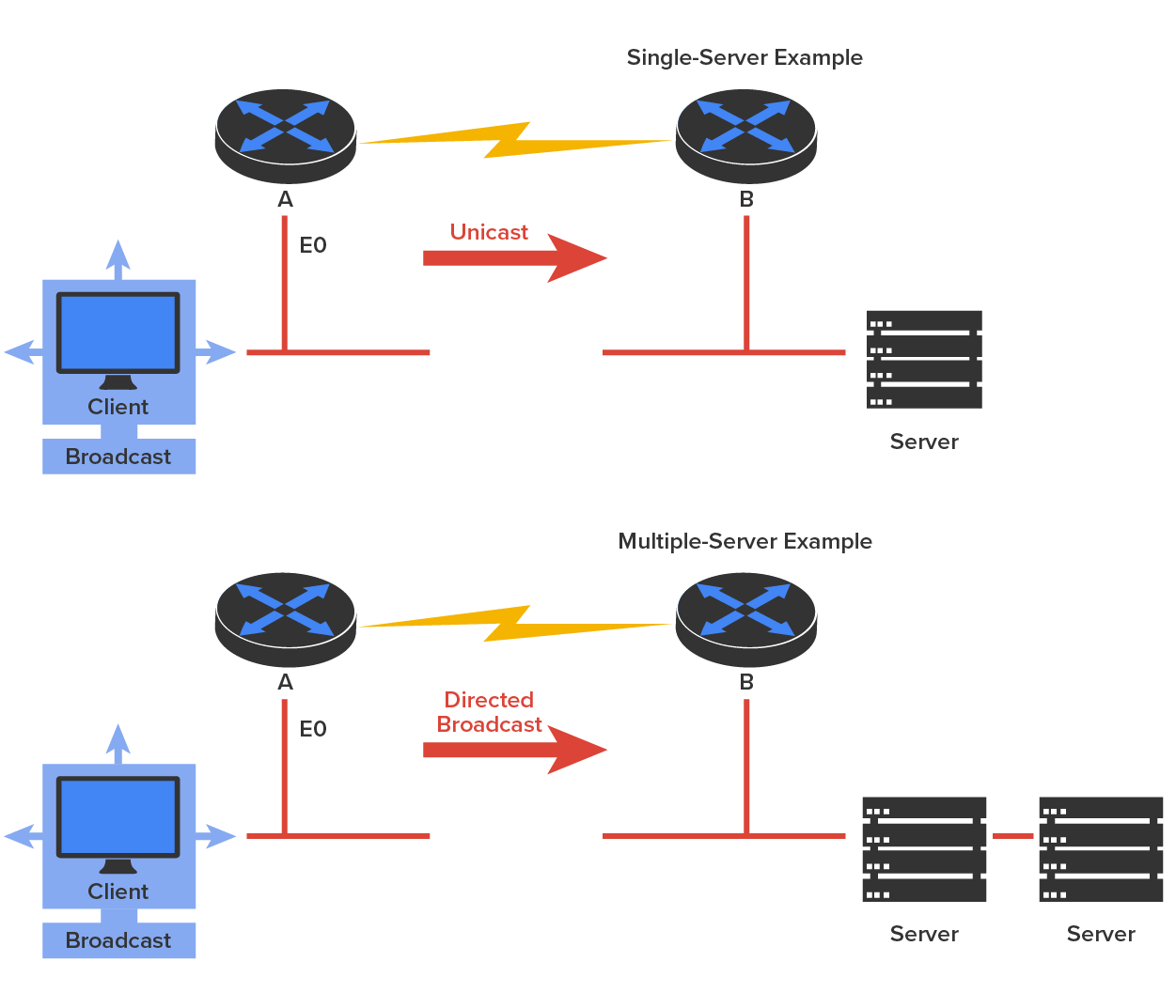
There’s a way around this problem, however. In the diagram above, Router A is configured with the IP helper address command on Interface E0 of the router. Whenever Interface E0 receives a broadcast request, Router A will forward that request as a unicast (which means that instead of a broadcast, the packet now has the destination IP address of the DHCP server).
So, as shown in the diagram, you can configure Router A to forward these requests and even use multiple DHCP servers for redundancy. This works because the router has been configured to forward the request to a single server using a unicast or by sending the request to multiple servers via a directed broadcast.
The following screenshot shows a Windows server’s DHCP configuration utility, where you can configure Scope Options.
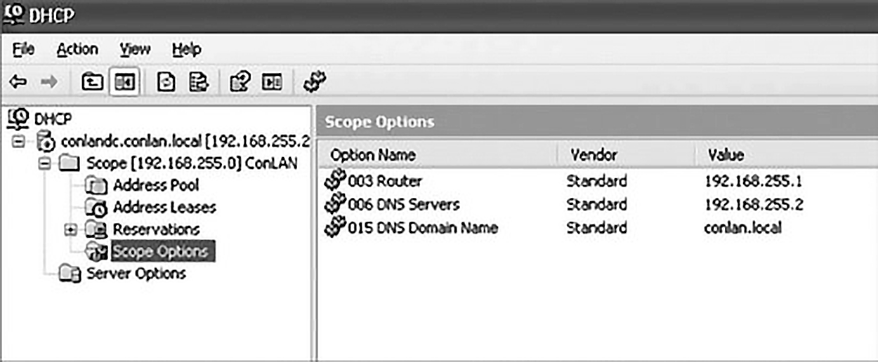
A scope is a range of IP addresses. Scope Options provide IP configuration for hosts on a specific subnet. Below Scope Options, you will find Server Options; these options provide IP information for all scopes configured on the server.
A DHCP client requests an IP address, a subnet mask, and a default gateway, and the DHCP server responds to the client request. You will learn about IP addressing later in the course. DHCP may also supply a lot of other information to the client as well.
Let us take a look at a DHCP client request on an analyzer. The screenshot below shows the options that the client is requesting from the DHCP server.
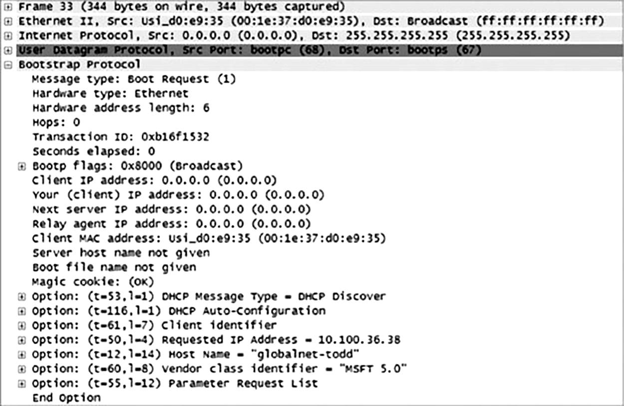
First, you can see that the client is “requesting” a certain IP address, because this is the IP address it received from the server the last time it requested an IP address. Take a look at what the server’s response is. The screenshot below shows the DHCP server response.
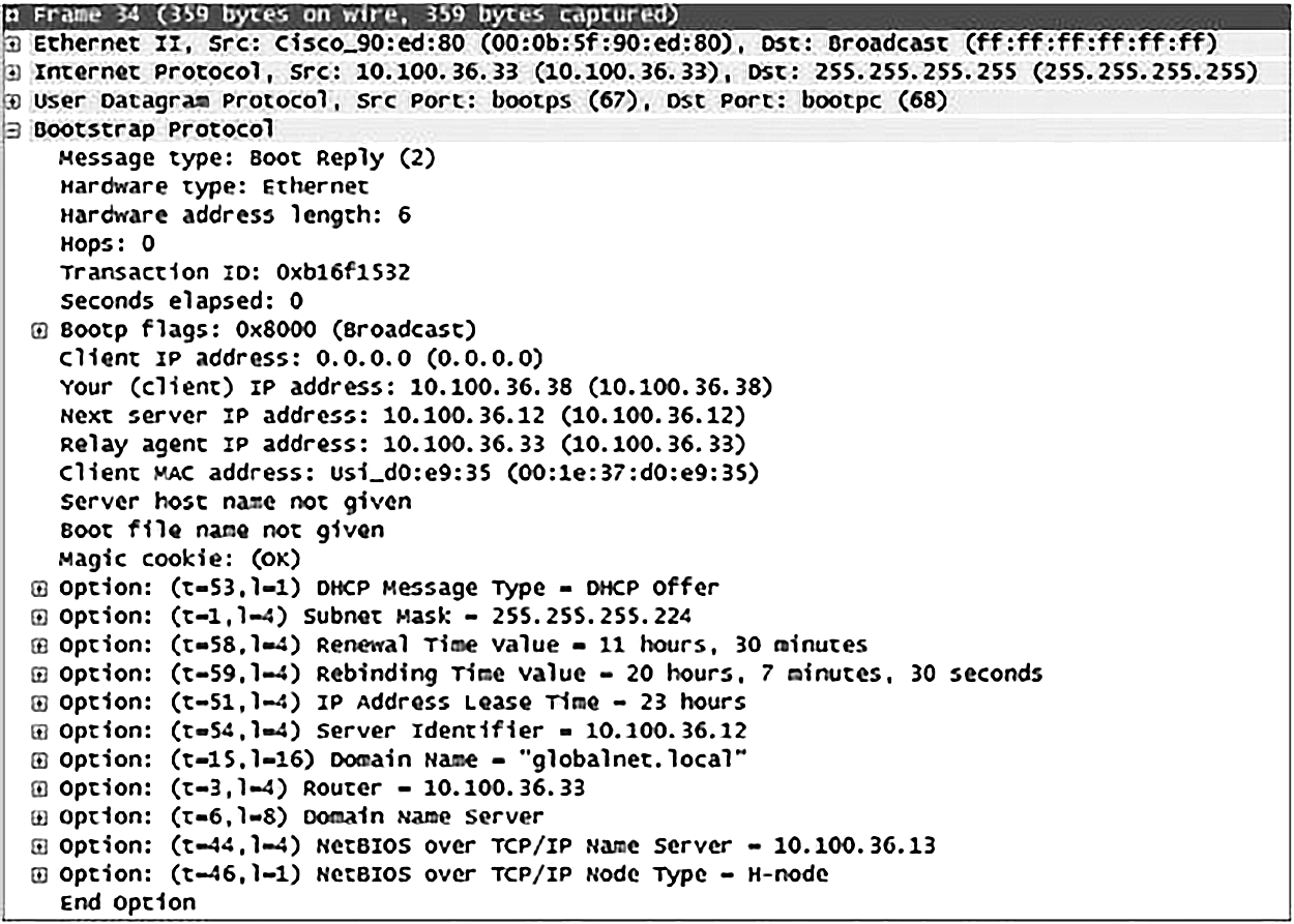
The client is going to get the IP address that it asked for (10.100.36.38), a subnet mask of 255.255.255.224, a lease time of 23 hr (the amount of time before the IP address and other DHCP information expire on the client), the IP address of the DHCP server, the default gateway (router), the Domain Name Service (DNS) server IP address (it gets two), the domain name used by DNS, and some network basic input/output system (NetBIOS) information (used by Windows for name resolution).
Source: This content and supplemental material has been adapted from CompTIA Network+ Study Guide: Exam N10-007, 4th Edition. Source Lammle: CompTIA Network+ Study Guide: Exam N10-007, 4th Edition - Instructor Companion Site (wiley.com)