Table of Contents |
In previous tutorials, you have learned about various types of network media and connections, so it is time to learn about some of the devices they hook up to that are commonly found on today’s networks.
A network interface card (NIC) is installed on your computer to connect, or interface, your computer to the network. It provides the physical, electrical, and electronic connections to the network media. The NIC resides at the data link layer (Layer 2) of the OSI Model because the information it uses for communication, the MAC address, resides on the data link layer.
An NIC is either an expansion card or built right into the computer’s motherboard. Today, almost all NICs are built into the computer motherboard, but there was a time when all NICs were expansion cards that plugged into motherboard expansion slots. In some notebook computers, NIC adapters can be connected to the USB port or through a mini PCle or M.2 card slot.
The photograph below shows a PCle 100 Mbps Ethernet NIC.
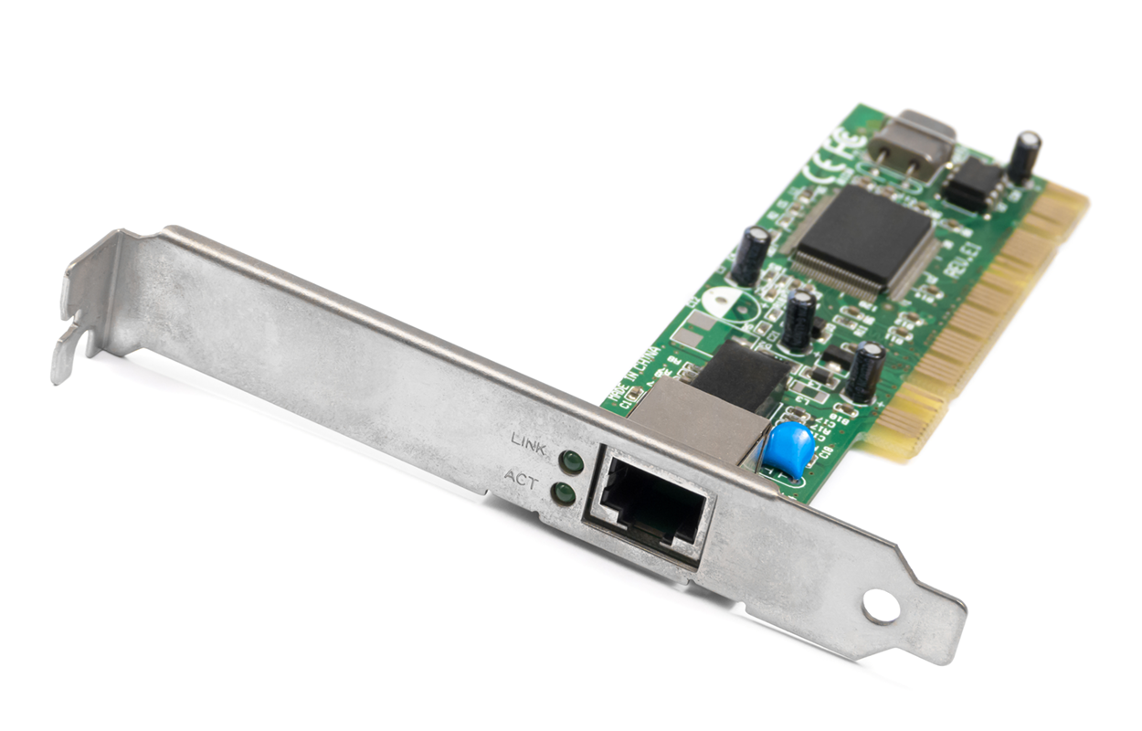
NICs today usually have one, two, or more LEDs; one, usually green, is called a link light, indicating that an Ethernet connection has been established with the device on the other end of the cable, and it flickers when traffic is being passed back or forth. The others usually indicate the speed of the connection: 10, 100, or 1000 Mbps. There is no universal standard for NIC LEDs, so check the manual to familiarize yourself with the ones you are working with. A blinking LED means the NIC is receiving a proper signal from the hub or switch. It can also indicate connectivity to, and detection of, a carrier on a segment. The other LED is aptly named the activity LED, which tends to flicker constantly. The activity indicates the intermittent transmission and reception of frames arriving at the network or leaving it.
A hub is a device that operates at the Layer 1 (physical) of the OSI model. A hub connects all the segments of the network together in a star topology Ethernet network. A hub has no intelligence, which means it does not interpret that data traffic in any way. Each device in the network connects directly to the hub through a single cable and is used to connect multiple devices without segmenting a network.
Any transmission received on one port will be sent out to all the other ports in the hub, including the receiving pair for the transmitting device, so that the Carrier Sense Multiple Access with Collision Detection (CSMA/CD) on the transmitter can monitor for collisions.
EXAMPLE
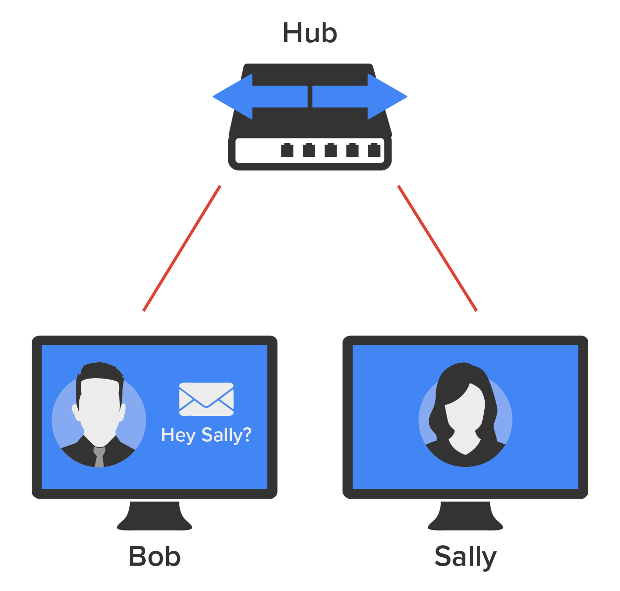
If one station sends a transmission, all the other stations will receive it; yet, based on the address found in the frame, only the intended recipient will process it. This arrangement simulates the physical bus that the CSMA/CD standard was based on, and it is why we call the use of a hub in an Ethernet environment a physical star/logical bus topology.The diagram below depicts a typical hub as you might find it employed within a small network. Since there are only two users, there is no problem in using a hub here. However, if there were many users, every station would receive Bob’s request to send information in a packet to Sally. Most of the time, hubs really are not recommended for corporate networks because of their security limitations.
A hub is essentially a multiport repeater that is incapable of recognizing frames and data structures. A transmission sent out by any device on the hub will be repeated to all devices connected to it. And just as in a physical bus topology configuration, any two or more of those connected devices can potentially cause a collision with each other, which means that this hardware device will create a LAN with the most network traffic collisions. Hubs are not recommended for use in today’s corporate network for this reason.
A repeater is a simple two-port device used to mitigate the effects of attenuation (that is, signal loss) by retransmitting signals to enable multiple cable segments to be connected together.
A bridge is a Layer 2 (data link) network device that connects two similar network segments together. Its primary function is to keep traffic separated on either side of the bridge, separating collision domains, as pictured below.
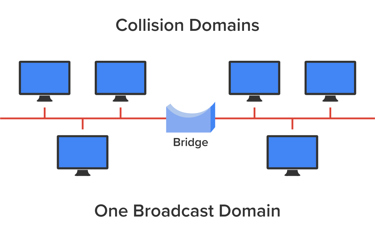
What we can see here is that traffic is allowed to pass through the bridge only if the transmission is intended for a station on the opposite side. The main reasons you would place a bridge in your network would be to connect two segments or to divide a busy network into two segments. Because bridges use MAC addresses to make forwarding decisions, they are considered Layer 2 devices.
Bridges are software-based legacy devices. Today, given the advances in technology, you would use a switch, which is a hardware-based, multiport bridge. In fact, the terms bridge and switch are often used interchangeably because the two devices use basically the same bridging technologies.
Switches connect multiple segments of a network together much like hubs do but with three significant differences. These include the following:
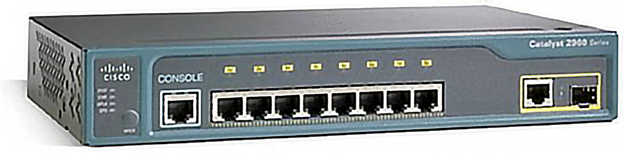
The photograph below shows a typical low-cost Ethernet switch. It looks a lot like a hub. However, switches can come in very large sizes that are expensive. Switches that can perform the basic switching process and do not allow you to configure more advanced features, like adding an IP address for telnetting to the device or adding VLANs, are called unmanaged switches. Others, like Cisco switches that do allow an IP address to be configured for management with such applications as SNMP and do allow special ports to be configured (as in VoIP), are called managed switches. Managed switches are designed to support enterprise IT environments.
That is as far as we are going with switches right now. You will study them in more detail later in the course. For now, you can think of a switch as a faster, smarter bridge that has more ports.
A router is a Layer 3 (network) device used to connect different networks together, combining them into what we call an internetwork. Routers separate broadcast domains. A well-configured router can make intelligent decisions about the best way to get network data to its destination. It gathers the information it needs to make these decisions based on a network’s particular performance data. As routers use IP addresses to make forwarding decisions, they are considered Layer 3 devices.
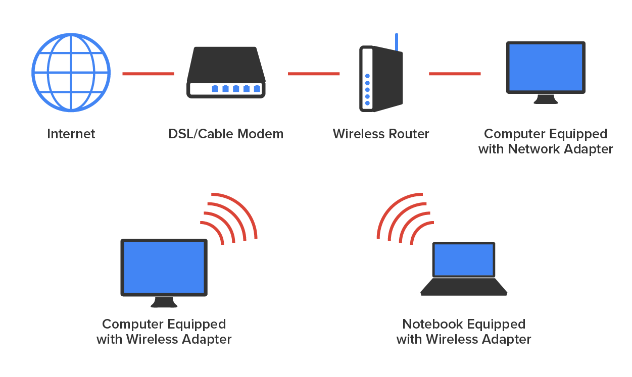
The diagram below shows a small office, home office (SOHO) router that provides wired and wireless access for hosts and connects them to the Internet without any necessary configuration.
Routers can be multifaceted devices that behave like computers unto themselves with their own complex operating systems—for example, Cisco’s Internetworking Operating System (IOS). You can even think of them as CPUs that are totally dedicated to the process of routing packets. And due to their complexity and flexibility, you can configure them to perform the functions of other types of network devices (like firewalls, for example) by simply implementing a specific feature within the router’s software.
In the next tutorial, we will discuss additional common network connectivity devices.
Source: This content and supplemental material has been adapted from CompTIA Network+ Study Guide: Exam N10-007, 4th Edition. Source Lammle: CompTIA Network+ Study Guide: Exam N10-007, 4th Edition - Instructor Companion Site (wiley.com)