Table of Contents |
The physical media that carry signals representing data reside at Layer 1 of the OSI model. The most basic physical medium is a cable, also known as a “wire,” that is made of copper or glass. Most data networks are wired, and even wireless networks that work using the radio spectrum typically depend on a cabled infrastructure.
Coaxial cable, commonly called “coax” for short, is a legacy cable system that is primarily used today to build cable television networks. It is no longer widely used to build Ethernet LANs, even though the Ethernet protocol was originally designed to work on a coaxial cable bus topology. Coaxial cable is relatively heavy, difficult to install, and expensive when compared to twisted-pair cable, which we will cover later in this lesson. Another reason that we no longer build LANs with coaxial cable is that it utilized a physical bus topology, which you may recall is not as fault tolerant as a star-wired topology.
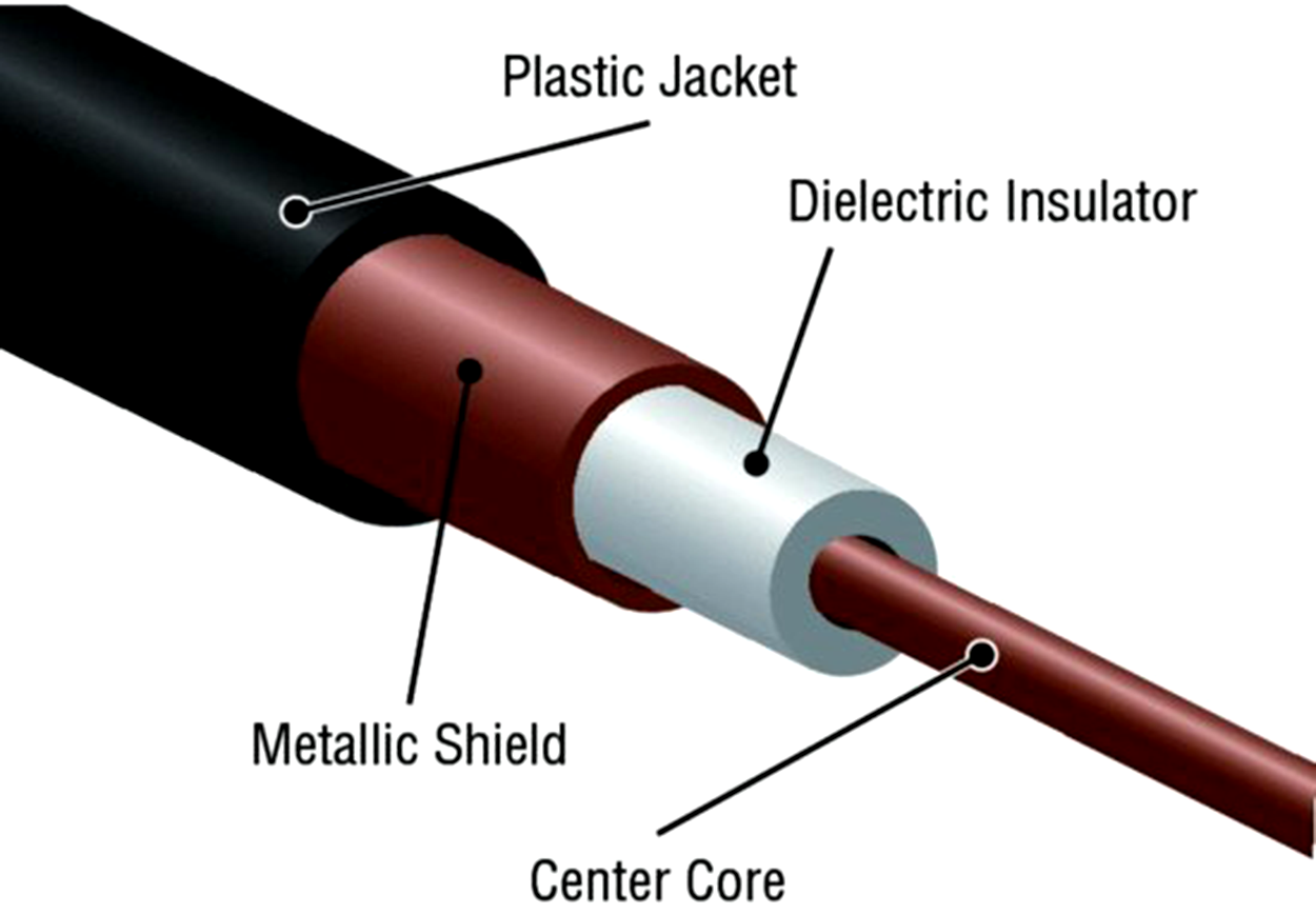
Coaxial cable contains a center conductor made of copper that is surrounded by a plastic jacket with a braided shield over it. A plastic such as polyvinyl chloride (PVC) or fluoroethylene propylene (FEP) covers this metal shield. The FEP-type covering is frequently referred to as a plenum-rated coating.
Thin Ethernet, also referred to as Thinnet or 10Base2, is a thin coaxial cable. It is basically the same as thick coaxial cable, except that it is only about 5 mm, or 2/10 in., in diameter. Thin Ethernet coaxial cable is Radio Grade 58, or just RG-58. The figure below shows an example of Thinnet. This cable’s connector is called an F-type connector.
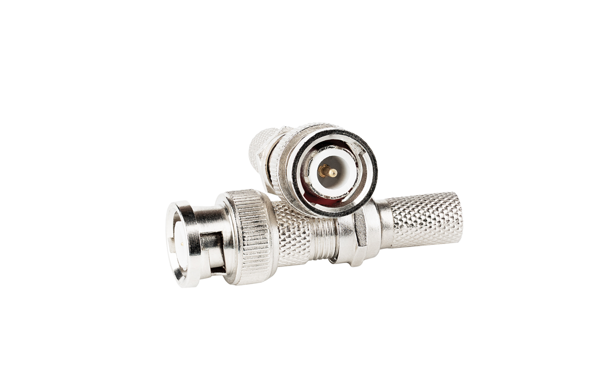
You can attach a BNC connector to the cable with a crimper that looks like a specialized pair of pliers and has a die to crimp the connector. A simple squeeze crimps the connector to the cable. You can also use a screw-on connector, but we avoid doing that because it is not as reliable. You can use a BNC coupler to connect two male connectors together or two female connectors together.
The F connector, or F-type connector, is a form of coaxial connector that is used for cable TV. It has an end that screws to tighten the connector to the interface. It resembles the RG-58 mentioned earlier.
Twisted-pair cable is widely popular for building LANs today, because it is relatively lightweight, easy to install, and inexpensive when compared to coaxial cable. Twisted-pair cable supports the star topology, which is more fault tolerant than a coaxial cable bus topology.
Twisted-pair cable consists of multiple individually insulated wires that are twisted together in pairs. Sometimes, a metallic shield is placed around them, hence the name shielded twisted pair (STP), which reduces signal loss caused by electromagnetic interference (EMI). Cable without outer shielding is called unshielded twisted pair (UTP), and it is used in twisted-pair Ethernet.
Ethernet cable types are described using a code that follows this format:  . The N refers to the signaling rate in megabits per second.
  stands for the signaling type—either baseband or broadband—and the X is a unique identifier for a specific Ethernet cabling standard.
Here is an example of the 1000BaseT standard. The 1000 tells us that the transmission speed is 1,000 Mbps (megabits per second). The word “Base” is short for baseband transmission, which means that the cable has only one communication channel. The “T” is short for “twisted pair.” So, why are the wires in this cable type twisted? When electromagnetic signals are conducted by copper wires in close proximity—like inside a cable—it causes interference called crosstalk. Twisting two wires together as a pair minimizes the interference and even protects against interference from outside sources.
UTP cable is rated in the following categories.
Two twisted wire pairs (four wires). It is the oldest type and is only voice grade—it is not rated for data communication. People refer to it as plain old telephone service (POTS). Before 1983, this was the standard cable used throughout the North American telephone system. POTS cable still exists in parts of the Public Switched Telephone Network (PSTN) and supports signals limited to the 1-MHz frequency range.
Four twisted wire pairs (eight wires) with three twists per foot. This type can handle transmissions up to 16 MHz. It was popular in the mid-1980s for Ethernet of up to 10 Mbps , but it is now limited to telecommunications equipment and, again, is obsolete for networks.
Four twisted wire pairs (eight wires), used for 100BaseTX (two-pair wiring) and rated at 100 MHz.
Four twisted wire pairs (eight wires), recommended for 1000BaseT (four-pair wiring) and rated for 100 MHz but capable of handling the disturbance on each pair that is caused by transmitting across all four pairs at the same time—a feature that is needed for Gigabit Ethernet. Any category below 5e should not be used in today’s network environments.
This picture shows a basic Category 5e cable with the four wire pairs twisted to reduce crosstalk.
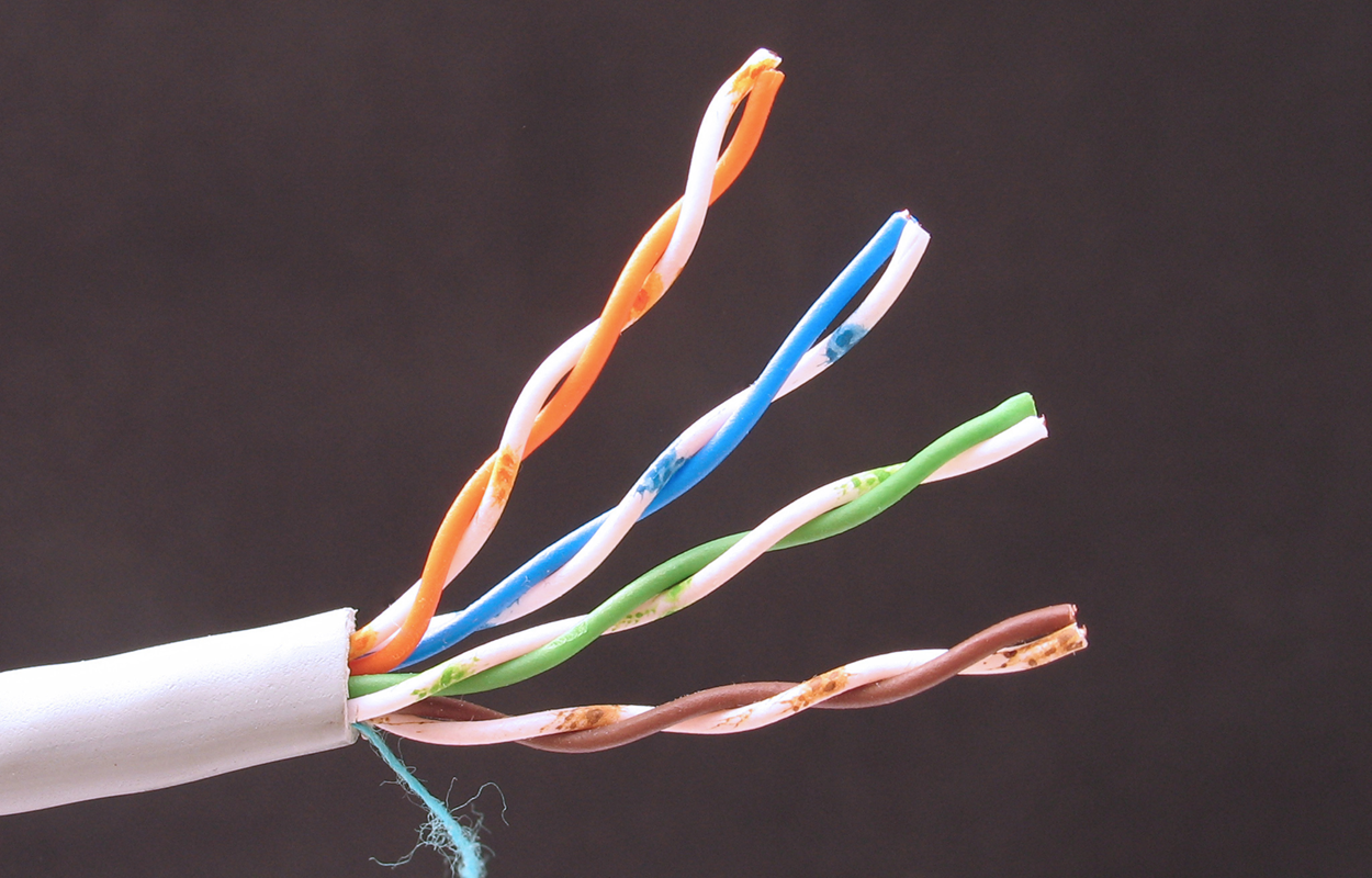
Four twisted wire pairs (eight wires), used for 1000BaseTX (two-pair wiring) and rated at 250 MHz. Category 6 became a standard in June 2002. You would usually use it as a riser cable to connect floors to each other. If you are installing a new network in a new building, there is no reason to use anything other than Category 6 UTP cabling as well as running fiber-optic cable between floors. You will learn about fiber-optic cable in the next lesson.
A basic Category 6 cable has a reduced maximum length when used for 10GBaseT; however, Category 6a cable, or Augmented Category 6, is rated at 500 MHz and has improved crosstalk characteristics, which allows 10GBaseT to be run for up to 100 m. The most important point is a performance difference between the Electronic Industries Alliance and Telecommunications Industry Association (EIA/TIA) component specifications for the NEXT (near-end crosstalk) transmission parameter.
Although not recognized by the EIA/TIA, Category 7 cable, or Cat 7, allows 10 Gigabit Ethernet over 100 m of copper cabling. The cable contains four twisted copper wire pairs, just like the earlier standards. Cat 7 cables are double shielded to better mitigate crosstalk and EMI.
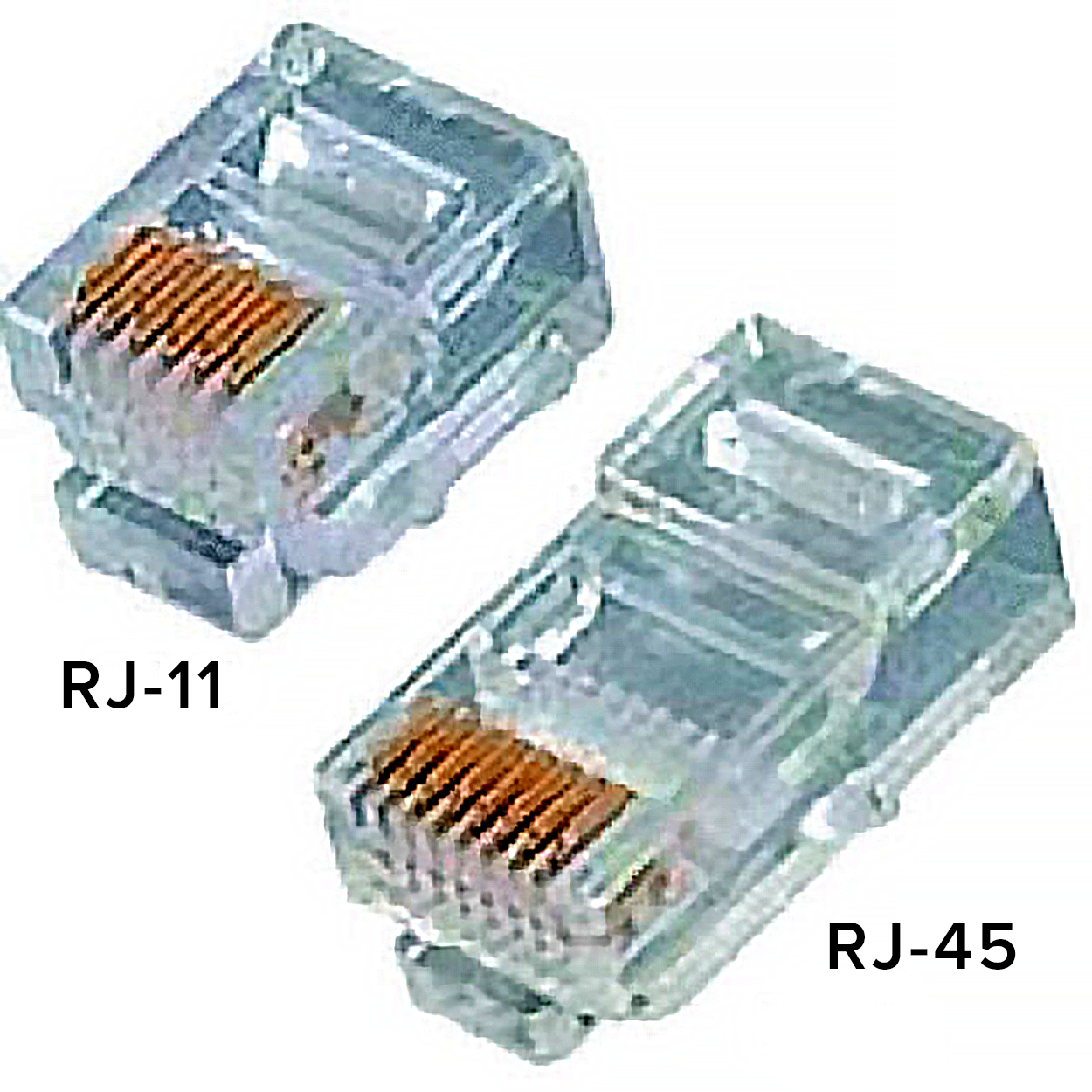
BNC connectors will not fit very well to UTP cable, so you need to use a registered jack (RJ) connector, which you are familiar with because most telephones are connected with them. The connector used with UTP cable is called RJ-11 for twisted-pair cables that use four wires; RJ-45 has four pairs (eight wires), as shown below.
The diagram below shows the pin-outs used in a typical RJ-45 connector. As a reminder of the wiring standard, please see the diagram below:
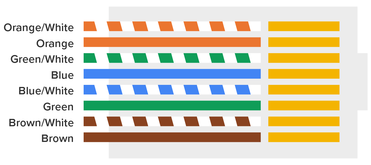
Most of the time, UTP uses RJ connectors, and you use a crimper to attach them to a cable, just as you would with BNC connectors. The only difference is that the die that holds the connector is a different shape. A crimper is a tool for attaching a network connector to the end of a network cable. Higher-quality crimping tools have interchangeable dies for both types of cables. We do not use RJ-11 for LANs, but we do use them for home landline phones and digital subscriber line (DSL) connections. RJ-45 is mainly used in LANs with short distances, typically up to 100 m, and uses unshielded wiring.
Source: This content and supplemental material has been adapted from CompTIA Network+ Study Guide: Exam N10-007, 4th Edition. Source Lammle: CompTIA Network+ Study Guide: Exam N10-007, 4th Edition - Instructor Companion Site (wiley.com)